LAB Documentation Communication Protocol Operating instructions for SIMDOS RC Plus Before operating the pump and the accessories, please read the operating instructions on the web site (www.knf.
KNF FLODOS AG Wassermatte 2 6210 Sursee, Schweiz Tel +41 (0)41 925 00 25 Fax +41 (0)41 925 00 35 www.knf.
Communication protocol Index 1 Index 1 Index ................................................................................... 3 2 General ............................................................................... 4 3 Initial start-up .................................................................... 5 4 Universal commands ....................................................... 6 5 Interface parameters ........................................................ 6 6 Data format ...........
General Communication protocol 2 General The SIMDOS RC Plus pumps can be controlled by using the standard RS232 serial interface (COM1, COM2, … ). The RS232 serial interface allows one pump to be controlled by a PC based software tool. Any of the commands listed in this document can be carried out as single commands for pump control or verification purpose. This may be of help for customers, who want to develop their own pump control tool.
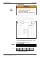
Communication protocol Initial start-up 3 Initial start-up WARNING Danger of automatic start-up The pump starts up by itself and without warning. Do not transmit a start command until the system has been tested and is ready for operation Mark remote-controlled pumps Before start-up, check that hoses and equipment are leak-tight and working properly Do not operate the pump with hazardous media 1. switch on the pump 2. Remove protective caps from RC connector plug. 3.
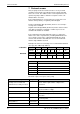
Universal commands Communication protocol 4 Universal commands The address number 99 has a special function. Commands, which don’t require an answer, can be sent to address 99. The command will be carried out by all pumps. This enables synchronized functions such as the start of all pumps at once. 5 Interface parameters The pump is permanently set to the following values: Name Value Baud Rate 9600 Baud Data Bits 8 Parity No Stop Bit 1 Handshake: There’s no monitoring.
Communication protocol Data format 6 Data format Each transmission packet consists of the following bytes: Transmit Name Size Example STX Address 1 Byte 2 Cmd str 2 Bytes 0 ETX 3 – 10 Bytes 0 ? S LRC 1 Byte 1 Byte 3 36 I STX (02h) Start of Text Address Pump address ‘00’ – ‘99’ ASCII, can be set on the pump command string Order of ASCII symbol according to command (cmd str) description ETX (03h) End of Text LRC Checksum Each receiver packet consists of the following bytes: Recei
Protocol answer Communication protocol 7 Protocol answer First, the pump checks the formal correctness of any received command. The Format as described in this document and LRC have to be correct. The address in the received packet has to be equal to the pump’s address. After the acceptance of the command, it will be executed. If the command has been executed, the processing of the command is either positively or negatively acknowledged.
Communication protocol Operation modes and their limitations NOTICE It is not allowed that two pumps can send their answers simultaneously The protocol answer can be deactivated (see command SPn). In this case no ACK or NACK sign is returned. The reply for commands that asked for information is always returned. 8 Operation modes and their limitations MS==0: Run Mode DT: unused DV: unused RV is forced to be within the interval [RVmin, RVmax] by the firmware.
Commands Communication protocol 9 Commands 9.1 10 Function list 9.1.1 Mode select: Run-mode / Dispense-mode .................. 11 9.1.2 Start, Stop, Prime/Drain ................................................. 12 9.1.3 Run mode flow rate µl/min............................................. 13 9.1.4 Dispense mode dispense volume µl ............................ 15 9.1.5 Dispense mode time for dispensing a volume .......... 16 9.1.6 Dispense mode: number of volumes...........................
Communication protocol Commands 9.1.1 Summary: Mode select: Run-mode / Dispense-mode Selects the active operating mode of the pump.
Commands Communication protocol 9.1.2 Summary: Start, Stop, Prime/Drain To initiate primary pump function. Start pumping, stop pumping, start Prime/Drain cycle.
Communication protocol Commands 9.1.3 Summary: Run mode flow rate µl/min. Sets the set value for the flow rate in Run mode. The unit is µl/min. Set command Command String RVnnnnnnnn Command name: RV Parameter value: nnnnnnnn Example: (8 digits, right adjusted) RV00020000 ⇒ 20’000 µl/min SIMDOS10 nnnnnnnn Function 0...99’999’999 Set value for the flow rate [µl/min] in Run mode 00’100’000 FEM 1.10 Maximum accepted value (NACK if higher) 00’001’000 FEM 1.
Commands Communication protocol Display on Pump User Interface: SIMDOS10 nnnnnnnn Display 1.0 … 100.0 Volume nnn.n ml/min (when in Run mode MS = 0) SIMDOS02 nnnnnnnn Display 0.03 … 20.00 Volume nn.nn ml/min (when in Run mode MS = 0) Power OFF behavior: Value of RV is saved Auto-start Power OFF behavior: Value of RV is saved Remarks: 14 Take notice of the limits! See chapter 8.
Communication protocol Commands 9.1.4 Summary: Dispense mode dispense volume µl Sets the set value for the dispense volume in Dispense-mode. The unit is µl. Set command Command string DVnnnnnnnn Command name: DV Parameter value: nnnnnnnn Example: (8 digits, right adjusted) DV00020000 ⇒ 20’000 µl SIMDOS10 nnnnnnnn Function 0...
Commands Communication protocol 9.1.5 Summary: Dispense mode time for dispensing a volume Sets the set value for the time to dispense a volume in Dispense mode. Set command Command string: DThhmmssss Parameter name: DT Parameter value: hhmmssss Example: (8 digits, [hh:mm:ss.ss] “h”: hour, “m”: minute, “s”:seconds, “.
Communication protocol Commands Remarks: Take notice of the limits! See chapter 8. NOTICE The pump will only accept this dispense time, as long as it is between the pump internal min. and max. time for dispensing a selected basic dispense volume, otherwise the pump will set the internal min. or max. time. A simple read back helps to check the actual dispense time. Time resolution is 1.00s.
Commands Communication protocol 9.1.6 Summary: Dispense mode: number of volumes The number of cycles, that the given volume shall be dispensed, is defined Set command Command string: DNnnnnn Command name: DN Parameter value: nnnnn Example (5 digits, right adjusted) DN00050 ⇒ 50 cycles nnnnn Function 0 Function off 1 Cyclic dispensing is deactivated 2...
Communication protocol Commands 9.1.7 Summary: Dispense mode: Break time between volumes Break time between two programmed dispense cycles Set command Command string: DBnnnnn Parameter name: DB Parameter value: nnnnn Example: (5 digits, right adjusted) DB00010 ⇒ 10 seconds break time nnnnn Function 1...5999 Break time in seconds Read Command Command string: Answer: Example: ?DB nnnnn (5 digits, right adjusted) Transmit ?DB Receive 00010 ⇒ 10 seconds break time nnnnn Meaning 1...
Commands Communication protocol 9.1.8 Summary: Actual run or dispense time counter. Time counter of the Dispense mode (and Run mode). Counter resets to 0 and starts at dispense start or run start Set command Command string: No command string Parameter name: -- Parameter value: -- Example: -- Read command Command string: Answer: Example: ?TT hhmmssss 5 digits, right adjusted [hh:mm:ss.ss] “h”: hour, “m”: minute, “s”:seconds, “.
Communication protocol Commands 9.1.9 Summary: Actual run or dispense volume counter µl Volume counter of the Dispense mode (and Run mode).
Commands Communication protocol 9.1.10 Analog control signal type selection Summary: Selects the analog signal type Set command Command string: RAn Parameter name: RA Parameter value: n (1 digit, right adjusted) RA2 ⇒ Analog signal 4…20mA Example: n Function 0 Analog signal 0…10V (Factory default) 1 Analog signal 0…20mA 2 Analog signal 4…20mA 3 Analog signal 0..
Communication protocol Commands 9.1.11 Flow rate range selection for analog input Summary: Sets one of the three flow rate ranges Set command Command string: RBn Parameter name: RB Parameter value: n (1 digits, right adjusted) RB2 ⇒ flow rate range is set to 0.15 – 15%. Example: n flow rate range 0 1 – 100% of full scale 1 0.3 – 30% of full scale 2 0.
Commands Communication protocol 9.1.12 Digital input 1 function Summary: Selects the function of the digital input 1.
Communication protocol Commands 9.1.13 Digital input 2 function Summary: Selects the function of the digital input 2.
Commands Communication protocol Read command Command string: Answer: Example: ?L2 nn (2 digits, right adjusted) Transmit ?L2 Receive L201 ⇒ Digital input 2, configured for level controlled start/stop signals nn Meaning 00 Signal 2: Off (Factory default) 01 level controlled: Start/stop 06 edge controlled: Start/stop 08 Pump Error reset & Pump Stop on signal edge.
Communication protocol Commands 9.1.
Commands Communication protocol 9.1.
Communication protocol Commands 9.1.16 Customer level measured calibration volume Summary: Customer level calibration based on Run mode flow rate or Dispense mode volume Set command Command string: CFnnnnnnnn Parameter name: CF Parameter value: nnnnnnnn (8 digits, right adjusted) CF 00000100 ⇒ 100 µl or 100 µl/min, it depends on the mode of operation Example: n Function 0...
Commands Communication protocol 9.1.17 Customer level calibration factor % Summary: Customer level calibration factor for pump stroke volume Set command Command string: CHnnnnn Parameter name: CH Parameter value: nnnnn (5 digit, right adjusted) CH08000 ⇒ Minimum accepted value 80%, the pump is calibrated to the lowest range nnn.nn Function Example: 0...999.99 Percentage of the factory calibrated pump stroke volume 080.00 Minimum accepted value 80% (NACK if lower) 120.
Communication protocol Commands 9.1.
Commands Communication protocol 9.1.19 LCD display contrast Summary: Sets the contrast level of the LCD display. Set command Command string: LCnnn Parameter name: LC Parameter value: nnn (3 digits, right adjusted) LC060 ⇒ LCD Contrast 60% n Function 000 ...
Communication protocol Commands 9.1.20 Auto-start after power on Summary: Settings of automatic start after power off/switch off. With active Auto-start the pump will start automatically if one of the following actions takes place: • The power plug is attached to the pump • The pump is switched on NOTICE If any input control signal is configured the pump will stay in pause state until a start trigger is given.
Commands Communication protocol 9.1.21 Pump model and firmware version Summary: To recognize pump model and firmware version. Set command Command string: No command string Parameter name: -- Parameter value: -- Example: -- Read command Command string: Answer: Example: ?SV nnnnnnnnnn (10 char, right adjusted) Transmit ?SV Receive SV001021307 ⇒ FEM1.02 mit Firmware 1.307 pppppvvvvv Meaning 00110xxxxx FEM1.10 00102xxxxx FEM1.
Communication protocol Commands 9.1.22 Communication check function Summary: Communication check function. Returns pump address if communication works correctly.
Commands Communication protocol 9.1.23 Protocol answer setting Summary: First, the pump checks the formal correctness of any received command. The Format as described in this document and LRC have to be correct. The address in the received packet has to be equal to the pump’s address. After the acceptance of the command, it will be executed. If the command has been executed, the processing of the command is either positively or negatively acknowledged.
Communication protocol Commands 9.1.24 Initialize the pump (new start) Summary: Reset the pump similar to power OFF/power ON.
Commands Communication protocol 9.1.25 Pump reset to factory settings Summary: This function brings the pump back to the factory settings. • All the modified custom settings except pump address will be set back to the factory settings. • Any custom calibration values will be set back to the factory calibration values.
Communication protocol Commands 9.1.26 Pump status request Summary: Reads back the pump status: Set command Command string: No command string Parameter name: -- Parameter value: -- Example: -- Read command Command string: Answer: 1. Example: 2. Example: 3.
Commands Communication protocol Byte 2 Bit value System - status 0 [1] [ 0 ] motor not adjusted, [ 1 ] motor adjusted 1 [2] [ 0 ] I/O 1 input low, [ 2 ] I/O 1 input high 2 [4] [ 0 ] I/O 2 input low, [ 4 ] I/O 2 input high 3 [8] [ 0 ] motor not on UT, [ 8 ] motor on UT 4 [ 16 ] 5 [ 32 ] 6 [ 64 ] 7 [ 128 ] Byte 3 Bit value 0 [1] Run mode - status [ 0 ] RUN-mode stopped [ 1 ] RUN-mode started 1 [2] 2 [4] 3 [8] 4 [ 16 ] 5 [ 32 ] 6 [ 64 ] 7 [ 128 ] Byte 4 value Dispense mode - status Bit [
Communication protocol Commands 9.1.27 Pump address nn Summary: Sets the pump address for serial interface commands. Set command Command string: ADnn Parameter name: AD Parameter value: nn (2 digits, right adjusted) AD10 ⇒ Set the network address of the pump to 10 Example: nn Function 00 ... 98 Pump address Read command Command string: Answer: Example: ?AD nn (2 digits, right adjusted) Transmit ?AD Receive 10 ⇒ The network address of the pump to 10 nn Meaning 00 ...
Commands Communication protocol 9.1.28 Maintenance position Summary: Move to maintenance position. When this function is activated, the eccentric of the pump moves to a position where maintenance is easily possible.
Communication protocol Troubleshooting 10 Troubleshooting 10.1 Communication problems 1. Check if pump is powered 2. Check connectivity • Make sure that the cables are connected • Choose the COM port at the PC which is connected to the USB to R232 Adaptor 3. Check COM port interface settings (see Section 5) 4. Check pump address, the default address is 00 (see also section 9.1.22) 5.
11 Command Index IP Factory reset ..................... 38 ? K ?SI Communication check ....... 35 ?SSn Status request ................... 39 ?SV Pump type ......................... 34 ?TT Dispence time counter ....... 20 ?TV Dispense volume counter .. 21 KYn Start, Stop, Prime .............. 12 L ADnn Set network address .......... 41 L1nn Digital input 1..................... 24 L2nn Digital input 2..................... 25 LCnnn LCD contrast ..................... 32 LSn Language select ...............
KNF weltweit Niederlande KNF Verder B.V. Utrechtseweg 4a NL-3451 GG Vleuten Tel. 0031 (0)30 677 92 40 Fax 0031 (0)30 677 92 47 E-mail: info@knf-verder.nl www.knf-verder.nl Belgien, Luxemburg KNF Verder N.V. Kontichsesteenweg 17 B-2630 Aartselaar Tel. 0032 (0)3 8719624 Fax 0032 (0)3 8719628 E-mail: info@knf.be www.knf.be China KNF Neuberger Trading (Shanghai) Co., Ltd No. 36 Lane 1000 Zhang Heng Road Shanghai 201203, P.R. China Tel. 0086 (0)21 685 965 66 Fax 0086 (0)21 339 006 26 E-mail: info@knf.com.cn www.