Diaphragm metering pump SIMDOS ® FEM 1.10 KT .18 S S / RC .18 KT / TT / FT [Chapt. 4] 1.10 FEM / UFEM - / PMLxxxx / PLxxxx [Chapt. 1] Operating Manual It is important to read and comply with all instructions in this operating and installation manual. An additional letter before the FEM model code is a country-specific designation, with no technical relevance. KNF FLODOS AG Wassermatte 2 6210 Sursee, Switzerland Tel. +41 (0)41 925 00 25 Fax +41 (0)41 925 00 35 www.knf-flodos.ch info@knf-flodos.
Items included on delivery: KNF FLODOS AG Wassermatte 2 6210 Sursee, Switzerland Tel. +41 (0)41 925 00 25 Fax +41 (0)41 925 00 35 www.knf-flodos.ch info@knf-flodos.
SIMDOS diaphragm metering pump About this document 1. About this document 1.1. Use of the operating and installation manual The operating and installation manual forms an integral part of the pump. Please be sure to pass the manual on to the next owner of the device. Project pumps Specifications and instructions for customer-specific project pumps (model numbers beginning with “PL” or “PML”) may differ from those set down in the operating and installation manual.
Use SIMDOS diaphragm metering pump 2. Use 2.1. Intended use The pump is a fluid pumping and metering device. Operator’s responsibility Operating parameters and conditions The pump must be installed and operated only in accordance with the operating parameters and conditions described in Chapter 4, Technical data. Protect the pump from moisture. The pump may be operated only when fully assembled.
SIMDOS diaphragm metering pump 3. Safety Safety Note the safety notes in Chapter 6, Assembly and connection, and Chapter 7, Operation The pump is constructed according to the generally accepted rules of the technology, and occupational health and safety and accident prevention provisions. Hazardous situations with the possibility of injuries to the user or other persons, or damage to the pump or other property, may, however, occur during use of the device.
Safety SIMDOS diaphragm metering pump EU directives/standards The pumps are in accordance with the requirements of the guidelines 2011/65/EU (ROHS2) The pump complies with all relevant provisions of the following directives: the EC machinery directive 2006/42/EC, safety provisions of the EC low-voltage directive 2006/95/EC and the EC directive on electromagnetic compatibility 2004/108/EC.
SIMDOS diaphragm metering pump Technical data 4. Technical data 4.1. Pump materials For KT models: 1) Sub-assembly Pump head Valve plate / seals Diaphragm Housing Tab. 2: KT Material PP FFKM PTFE-coated PP 1) according to DIN ISO 1629 and 1043.1 For TT models: 1) Sub-assembly Pump head Valve plate / seals Diaphragm Housing Tab. 3: TT Material PVDF FFKM PTFE-coated PP 1) according to DIN ISO 1629 and 1043.1 For FT models: 1) Sub-assembly Pump head Valve plate / seals Diaphragm Housing Tab.
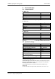
Technical data SIMDOS diaphragm metering pump 4.3. Accuracy / reproducibility Accuracy The accuracy of the metering pump is appropriately characterised by the maximum absolute error A and the maximum relative error B. max. inaccuracy ≤ A + B Error Absolute error A Relative error B Value ≤ ± 1‰ nominal value ≤ ±1.9% setting value Tab.
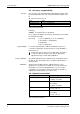
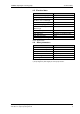
SIMDOS diaphragm metering pump Technical data 4.5. Electrical data Parameter Nominal mains voltage [V] Frequency [Hz] Maximum current consumption AC 100 V / 115 V / 240 V [A] Max. watt consumption [W] Pump DC voltage [V] Max. current consumption, DC RMS 24 V [A] Max. short-term peak current [A] Power supply protection Pump protection Pump protection type Power supply protection type Value 100–240 V AC +/- 10% 50–60 Hz 0.1 / 0.09 / 0.05 10 24 V DC 0.4 1.
Technical data SIMDOS diaphragm metering pump 4.7. External drive (RC version only) Parameter Value Analogue input Signal range 0–10 V, 4–20 mA, 0–20 mA Input resistance [Ω] 13.9 kΩ at 0–10 V 470 Ω at 4–20 mA 470 Ω at 0–20 mA 24 V DC Electric strength [V] TTL Digital input Signal range Electric strength [V] TTL Low level (ON) High level (OFF) Pull up at 24 V 24 V DC < 0.8 V = low > 2.
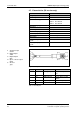
SIMDOS diaphragm metering pump 5. Structure and operation Structure and operation 5.1. Metering pump structure 1 2 3 4 5 6 7 8 9 STOP button START button Display Control knob Inlet Pump head Outlet Power supply plug External drive plug (RC version only) Fig. 2: Diaphragm pump 5.2. Operating principle 1 2 3 4 5 6 7 Exhaust valve Inlet valve Working chamber Diaphragm Eccentric Connecting rod Pump drive Fig.
Structure and operation SIMDOS diaphragm metering pump 100% flow rate 1% flow rate Fig. 4: Low-pulsation operating principle The characteristic curve for the suction and exhaust strokes can also be adapted to the medium by setting the appropriate fluid type (see section 7.13). 5.3. Metering pump functions Operating modes Continuous pumping In this case, the device pumps at a constant flow rate. Fig.
SIMDOS diaphragm metering pump Structure and operation 5.4. Functions overview Main menu 1. Flow rate 1–100 ml/min or metered volume 1–1,000 ml 2. Timeout/metering time 3. High-speed operation for priming or emptying 4. Pump calibration 5. Setting the pump for characteristics of the medium - Standard: Aqueous media - Degassing: Media with low boiling temperature - Visk100cSt: Media up to 100 cSt - Visk500cSt: Media up to 500 cSt 6. Go to system menu Fig. 8: Main menu System menu 7. Return to main menu 8.
Assembly and connection SIMDOS diaphragm metering pump 6. Assembly and connection All pumps must be installed only in accordance with the operating parameters and conditions described under Technical data (see Chapter 4). Note the safety instructions in Chapter 3. 6.1. Assembly Store at the assembly location prior to assembly so that the pump is at the same temperature as the surrounding environment. Dimensions Pump dimensions (see Fig. 10) Fig.
SIMDOS diaphragm metering pump Assembly and connection 6.2. Electrical connection Electrical connections must comply with relevant standards, directives, regulations and industry standards. 1. Connect the mains plug cable to the socket in the pump. 2. Plug the mains plug into a correctly installed and properly earthed mains socket. Fig. 11: Electrical connection The pump must be connected only to a correctly installed and properly earthed mains socket.
Assembly and connection SIMDOS diaphragm metering pump 6.4. Hydraulic connection Connected components All components connected to the pump must be designed for the hydraulic ratings of the pump (see Chapter 4). Hoses All hoses used must be designed for the maximum permitted operating pressure of the pump (see Chapter 4). All hoses used must have sufficient chemical resistance to the pumped fluids. Customer-specific pumps (PL, PML) The connections described below apply to standard products.
SIMDOS diaphragm metering pump Assembly and connection Cutting ring / hose connection fitting with threaded socket FEM 1.10FT, UFEM 1.10FT 1 2 3 4 5 6 7 Hose Threaded socket Teflon sealing tape Union nut Cutting ring Sealing ring Connector Fig. 13: 4/6 hose / cutting ring FT connection fitting 1. Remove protective covers from the connections. 2. Screw the threaded socket (2) with Teflon sealing tape (3) into the pump head. Do not apply excessive torque to the threaded socket.
Operation SIMDOS diaphragm metering pump 6.5. Shutdown On completion of the pumping operation, flush the entire system and the pump with a neutral fluid, then pump it empty. To ensure satisfactory start-up when the unit is again required, it is important to ensure that the pump is free of any crystallising, adhesive or curing media. Press the STOP button to end the pumping operation. Unplug the pump from the power supply. 6.6.
SIMDOS diaphragm metering pump Operation If it is possible that pressures in excess to the limits can occur it is important to take the necessary measures, e.g. a pressure relief valve or pressure sensor. For further assistance contact your local KNF specialist. Never apply positive pressure to the suction side of the pump. A small positive pressure of less than 0.5 m water column will cause the pump to block flow in the pumping direction.
Operation SIMDOS diaphragm metering pump Specified flow and unit Time counter Displays the set flow rate (1) if the unit (2) has been set on “ml/min”. Displays the metering volume (1) if the unit (2) has been set on “ml”. Displays the pump running time. Upward count (3) if no timeout has been programmed. Elapsed time display. Downward count (3) if a timeout (metering) has been programmed. Time remaining display. Volume meter Display of delivery volume (4) since last pump start-up.
SIMDOS diaphragm metering pump Operation 7.5. Starting the pump Press the “START” button. The unit will begin pumping. The triangle symbol will appear in the display. An externally driven pump will start only if the external pump signals allow a pump start-up (see Chapter 8). Fig. 19: Starting the pump 7.6. Interrupting a pumping operation Press the “START” button. The pumping operation is interrupted. The pause symbol will appear in the display.
Operation SIMDOS diaphragm metering pump 7.8. Entering settings Turn the control knob to move the display up or down. Fig. 22: Moving the operating menu up/down The lines in the middle of the display are enclosed in a frame, and can now be selected with the control knob. Fig. 23: Select the framed lines by pressing the control knob. The selected settings are marked with an inverted display. Now turn the control knob to change the value as required. Fig.
SIMDOS diaphragm metering pump Operation Ending the setting operation: Keep pressing the control knob until no values are selected (values marked with inverted display). Then turn the control knob until the main display can be seen at the top of the operating menu. Press the “STOP” button: this ends the input operation, and the display switches back to the main display. The pump will stop when this operation is carried out.
Operation SIMDOS diaphragm metering pump 7.9. Specified flow The specified flow function is used to set the desired flow rate or metering volume. Input Flow rate Metering volume Unit Setting range Millilitres per minute [ml/min] 1.0–100.0 Millilitres [ml] 1.0–1,000.0 Tab. 13: Specified flow Fig. 26: Specified flow To ensure precise results, it is necessary to calibrate the pump (see section 7.14).
SIMDOS diaphragm metering pump Operation 7.12. Priming This function is for rapidly priming and emptying the pump head and lines. Press the control knob and hold in place for the duration of the priming/emptying operation. The pump will run at a higher speed during this time. Fig. 30: Priming The priming function interrupts a metering operation that is currently in progress. 7.13. Fluid type The fluid type setting is used to adjust the pump characteristic curve for different types of fluid.
Operation SIMDOS diaphragm metering pump Viscosity up to 100 cSt Symbol: V This setting is for media with a viscosity up to approx. 100 cSt. The pump suction rate is reduced. The maximum flow rate is limited to 50 ml/min. Fig. 34: “Visk100cSt” fluid type Viscosity up to 500 cSt Symbol: H This setting is for media with a viscosity up to approx. 500 cSt. The pump suction rate is significantly reduced. The maximum flow rate is limited to 20 ml/min. Fig. 35: “Visk500cSt” fluid type 7.14.
SIMDOS diaphragm metering pump Operation 7.15. System settings Select “System” to bring up a second menu list for the entry of further pump settings. Fig. 38: System menu 7.16. Back to main menu System Click on “Back” to return to the main menu for entering pump default settings. Other options for returning to the main display are as follows: Press the “STOP” button: this ends the input operation, and the display switches back to the main display.
Operation SIMDOS diaphragm metering pump 7.18. Auto start System The “Auto start” setting defines the process for switching on the pump. Input Off Meaning Pump does not start automatically when the power supply to the pump is switched on. Pump starts automatically when the power supply to the pump is switched on. On Fig. 41: Autostart Tab. 15: Autostart When the “Autostart” option is on, this is indicated in the main display with the “AS” symbol (see Fig. 43).
SIMDOS diaphragm metering pump Operation 7.19. Contrast System This refers to the contrast setting for the display. Adjust the contrast if the display is poorly legible. Fig. 43: Contrast 7.20. Reset System The “Reset” function is used to reset the pump to its factory settings. Input No Yes Code Meaning No reset Pump is reset to its factory settings No function Tab. 16: Reset Fig.
RC version – external drive SIMDOS diaphragm metering pump 8. RC version – external drive External drive functions are available only in the RC version. Connection details and technical data are provided in sections 4.7 and 6.3. When external drive is activated, this is indicated in the main display with the “RC” (1) symbol (see Fig. 46).
SIMDOS diaphragm metering pump RC version – external drive Fig. 47: Analogue input START/STOP analogue signal Starting and stopping the pump with an analogue signal 1. Set the analogue input to the correct signal type. 2. Press “START” – the pump goes into “Pause” mode. 3. Apply analogue signal. The pump now starts operating, and goes into “Run” condition. 4. Reduce analogue signal to below off threshold – the pump stops and goes into “Pause” condition.
RC version – external drive SIMDOS diaphragm metering pump 8.2. Digital input 1, Start/Stop System The pump can be externally started and stopped via digital input 1. If digital input 1 is active, the pump can be started only via the digital input. If analogue control is also set, a valid analogue signal must be present. Control signals Fig. 48: Digital input 1 Input Off Level Meaning Digital input 1 not active Start/Stop according to signal level Pulse Start/Stop on signal pulse Signal -< 0.
SIMDOS diaphragm metering pump RC version – external drive Start/Stop level with timeout Start/Stop level with timeout 1. Set digital input 1 “In_1” to Level. 2. Press “START” – the pump goes into “Pause” condition. 3. Apply signal 1. The pump will start to operate when the level is connected to ground, and stop when the set time has expired. If the pump time counter has been activated, the pump cannot then be stopped with digital input 1. This input functions only for starting the pump.
RC version – external drive SIMDOS diaphragm metering pump 8.3. Digital input 2, Reset/Prime/Pedal switch Digital input 2 can be used for an externally activated error reset or fluid system priming operation. System The option Level and Impulse have the same function as the „Digital Input 1“which is mainly for use with the footswitch # 155872. Control signals Fig.
SIMDOS diaphragm metering pump RC version – external drive Digital input 2, Combined Combined The “Combined” setting activates the following functions on application of a signal to digital input 2: Interrupt a metering process Reset of pump errors on signal edge If the signal is applied for longer than 1 second, the pump will operate in “Prime” at high speed for the duration of the signal. Deletion of an active Master Stop (see section 7.
RC version – external drive SIMDOS diaphragm metering pump 8.4. Digital output System The digital output can be used to feed back a number of messages to the control system. The output is an open collector output (see section 4.6). Output signals Input Alarm Motor Fig. 55: Digital output Vol.End Mot.Pul. Vol.Pul.
SIMDOS diaphragm metering pump Maintenance 9. Maintenance 9.1. Maintenance plan Component Pump Pump head Pump diaphragm Intake filter (accessory) Maintenance interval Regular inspections for external damage or leaks. Clean if flow rate deteriorates, pump fails to create vacuum or will not run. Replace parts if necessary (see Chapter 11). - Change the diaphragm after 1000 hours of use. - Change the diaphragm if the flow rate changes or the pump leaks.
Maintenance SIMDOS diaphragm metering pump 9.3. Cleaning/replacing valve plates and pump diaphragm Prior requirements Tools and materials Pump must be switched off and mains plug removed from the socket. The pump must be free of any hazardous substances. Hoses must be disconnected from the pump head. Qty. 1 1 Tool/material Phillips screwdriver No. 1 Spare parts kit (see Chapter 11) Tab.
SIMDOS diaphragm metering pump 1 2 3 4 5 6 7 8 Maintenance Head bolt Cover plate Connecting plate Sealing washer Valve seat O ring Valve disk Spacer plate Fig. 57: Head, KT, TT Head, FT 1. Loosen four head bolts (1) and remove pump head as a complete unit. The pump diaphragm (12, Fig. 59) is now visible. 2. Pull apart the cover plate (2), connecting plate (3) and spacer plate (8). 3. Carefully remove the valve seats (5), remove sealing washers (4) (not present in FT head, see Fig.
Maintenance SIMDOS diaphragm metering pump Replacing pump diaphragm 9 10 11 12 Connecting rod Shim ring Support Pump diaphragm Fig. 58: Replacing the pump diaphragm 1. Grasp both sides of the pump diaphragm (12), lift it up and screw it out anti-clockwise. 2. Remove the support (11) and shim ring (10) from the threaded bolt of the diaphragm, and put aside in a safe place. 3. Inspect all parts for soiling, and clean if necessary. 4.
SIMDOS diaphragm metering pump Maintenance Refitting the pump head Fig. 59: Refitting the pump head 1. Place the sealing washers (4) in the appropriate recesses of the connecting plate (3) and spacer plate (8). 2. Place the O rings (6) and valve disks (7) on the valve seats (5) (see Fig. 60, middle). Check that the O rings and valve disks are correctly positioned. 3. Place the assembled valve seats (5+) to fit snugly into the connecting plate (3). Jammed valve seats may cause the valve to malfunction.
Troubleshooting SIMDOS diaphragm metering pump 10. Troubleshooting Instructions Safety note CAUTION WARNING Always remove the mains plug from the socket before carrying out any work on the pump. Health risk from hazardous substances in the pump. Some pumped media involve the possibility of corrosion damage or intoxication. Use protective equipment if necessary, e.g. protective gloves, goggles. Flush pump with a neutral fluid and then pump empty. Inspect the pump (see Tab. 25 and 26).
SIMDOS diaphragm metering pump Troubleshooting Low flow rate, pressure or vacuum Pump output not in accordance with technical data or performance specifications in data sheet. Possible cause Corrective action Presence of positive pressure Change pressure conditions. on the pressure side with simultaneous vacuum or positive pressure on the suction side. Cross-section of hydraulic lines Disconnect the pump from the system and determine output or connectors too narrow or values. constricted.
Spare parts and accessories SIMDOS diaphragm metering pump 11. Spare parts and accessories 11.1. Spare parts Spare part SIMDOS spare parts kit, valves and seals, all versions SIMDOS spare parts kit, KT head Order No. 160186 SIMDOS spare parts kit, TT head 160188 SIMDOS spare parts kit, FT head, FEM SIMDOS spare parts kit, KT head, UFEM SIMDOS spare parts kit, TT head, UFEM SIMDOS spare parts kit, FT head, UFEM 160189 160187 160190 160191 160632 Tab. 27: Spare parts 11.2.
SIMDOS diaphragm metering pump Decontamination statement 12. Decontamination statement Provision of a customer declaration identifying the pumped media and certifying that the pump has been properly cleaned (decontamination statement) is a prerequisite for any repair work on a pump carried out by KNF. Take a copy of this page. Enter the pump model, serial No.
KNF worldwide Benelux Netherlands KNF Verder B.V. Utrechtseweg 4a NL-3451 GG Vleuten Tel. 0031 (0)30 677 92 40 Fax 0031 (0)30 677 92 47 E-mail: info@knf-verder.nl www.knf-verder.nl Benelux Belgium, Luxembourg KNF Verder N.V. Kontichsesteenweg 17 B-2630 Aartselaar Tel. 0032 (0)3 8719624 Fax 0032 (0)3 8719628 E-mail: info@knf.be www.knf.be China KNF Neuberger Trading (Shanghai) Co., Ltd No. 36 Lane 1000 Zhang Heng Road Shanghai 201203, P.R. China Tel.