
Installation guide

Installation Guide P. 15
q Door Locks and Trunk Testing. Make sure each of these options respond to the
Transmitter (if installed).
q Starter Kill option. Sit inside the vehicle with all Doors closed. Arm the vehicle, then try
to start the Engine with the Key. They Engine should not start. If the Engine starts,
rewire the Starter Kill to reach proper operation.
q Valet Mode. Make sure the System is able to properly enter and exit Valet Mode. When
setting the System into Valet Mode, pressing the Lock button will lock the Doors without
activating the Starter Kill. (Refer to the User Guide for further information on Valet
Mode.)
q Idle Mode. Make sure the Vehicle properly enters and exits Idle Mode.
Most comebacks are the result of misunderstandings about how a product works or performs. Take
the time to properly explain all functions and features to the customers before they leave the
premises. Doing this will save time and money.
Closing Up
Use tie-wraps or screws to properly secure the system and keep the wiring away from any moving
parts such as the parking brakes or steering column shafts. Mount all switches in good and
accessible locations where they do not risk getting kicked or hit accidentally. Most comebacks are
the result of misunderstandings about how a product works or performs. Take the time to properly
explain all functions and features to the customers before they leave the premises. Doing this will
save time and money. Always make all your connections before plugging in the System, and be
sure to test all functions properly before closing up the installation. Make sure the warning label is
applied on a visible place under the hood.
Supplementary Information
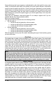
Fifth Relay Output (2nd IGN, ACC or CRANK)
Systems of this series are equipped with an
on-board high-current programmable 5
th
Relay that can be used to power a second
Ignition, Accessory or Crank wire.
The Unit uses 3 sets of pins; each set
corresponds to a specific function of the
output. In order to activate one of the three
possible functions, you must place the
Jumper (supplied) on one of the three sets
of pins and connect the 14 AWG wire to the
second IGN. / ACC. / CRANK wire of the
vehicle.
Caution!
Only one set of pins can be used at one time. Using more than one Jumper may
result in serious damage to the vehicle. The relay output rating on this unit is 25 A at
most. Defective OEM solenoid switches can sometimes draw up to 50 or 60 A, causing
the 30 A Fuse to blow. Always verify your circuit with an appropriate measuring device.
Clutch bypass
In order to remote start a manual-transmission vehicle, the clutch switch must be bypassed. Clutch
safety switch circuits can take many forms. The most common types are listed below. When testing
to determine the type of clutch circuit, it is recommended that you use a computer-safe logic probe.