TWO -WAY MANUAL STARTER S Y S T E M TRANSMISSION W I T H F U L L REMOTE A L A R M AS-6070 TW-A Installation Guide A note concerning the battery inside the transmitter: Depending on your usage of the transmitter, the battery can last anywhere between 3 to 6 months. When the battery is low, the transmitter will produce two beeps in a repetitive cycle. At that point you should replace your battery with a new one.
Table of Contents Table of Contents .......................................2 Introduction.................................................2 Included in the Kit.......................................2 Installation Points to Remember ................3 Harness Description ...................................4 Flashing the Hood Pin Switch ....................8 Remember:.................................................9 The Programming Assistance Button ........9 Caution ..........................................
The following is a list of components included in the kit: • 1 – Remote Starter and Alarm System • 1 – five-pin 18 AWG Harness (Main Control Unit Harness) • 1 – Antenna Interconnect Cable • 1 – twelve-pin 22 AWG Harness (Accessories Harness) • 1 – multi-channel 5-button Remote Control • 1 – two-pin 22 AWG Harness (Accessories Harness) • 1 – plug-in dual-zone Shock Sensor • 1 – parts bag: a Hood Pin-switch, a • 1 – plug-in L.E.D.
• Wiring a Clutch Bypass and a Transponder Module to the GROUND OUT WHEN RUNNING wire: At the junction point, where the GROUND OUT WHEN RUNNING wire “splits” and connects to each device, a diode is inserted on each of these lines. • Multiple or separate Door pin Connec tions: • When joining all Door Pins together to the Door Pin input wire of the System unit, each wire must be isolated with a diode to prevent feedback.
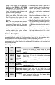
-pin Secondary Harness Wire Colour Function 1 BLACK (–) Chassis ground input 2 PURPLE (A.C.) Tachometer input 3 GREY (–) Hood Switch input 4 ORANGE (+) Brake Switch input 5 YELLOW (+) 12 V Parking Light output Description This wire must be connected to bare, unpainted metal (the Chassis or the true Body ground). It is preferable to use a factory ground bolt rather than a self- tapping screw. Screws tend to get loose or rusted over time and can cause erratic problems.
BLUE / WHITE 7 WHITE / ORANGE 8 ORANGE 9 PURPLE 10 WHITE 11 GREY P. 6 before every remote start. This input should be used in vehicles with positiveswitching Door pins or Dome Light circuits. Connect to the Dome Light wire that tests +12 V when a Door is open. Caution! The installer should use either the positive or the (+) Positive negative Door input. Never use both of them Door input simultaneously.
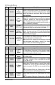
In diesel mode, this positive input will monitor the glow plug light: it will wait for up to 18 seconds until the glow-plug light goes out before allowing the system to proceed to cranking the engine. Connect to the side of the glow-plug light which is positive when the light is on. Note: the system will nevertheless proceed to cranking the engine if the glow-plug light is still on after the 18sec. delay (25 sec. when the run time is set to 30 min.).
Connect the glow-plug wire to the ignition wire only after the tach programming has been completed: connecting the glow-plug wire is one of the very last steps in the installation process. 2-Pin Harness Wire Colour 1 BLUE/ WHITE 2 YELLOW Function Description (–) AUX 2 output This 500 mA negative output can be programmed for one of the following Options: 1. Constant while the LOCK and UNLOCK buttons are pressed simultaneously, + 1 sec. after the buttons are released. 2.
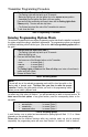
Remember: Once the Parking Lights are O N (solid), you have up to 20 seconds to select a submenu. If you do not select a sub-menu within 20 seconds, the System will exit Programming Mode and you will have to flash the Hood Pin switch once again. The Programming Assistance Button (A.k.a. the PAB.) Mounted on the system, this button can be used from within the vehicle instead of the hood pin switch in the engine compartment.
Transmitter Programming Procedure 1. Flash the Hood Pin switch (see Table 1) – The Parking Lights will stay ON for up to 20 seconds. – Before the lights go out, turn the Ignition Key to the IGNITION ON (RUN) position. – Immediately turn the Ignition Key back to the OFF position. Press and hold the LOCK button and keep it down until the Parking Lights flash 5 times quickly. The siren will also chirp twice. – The System has stored the code of the Transmitter into memory. 2. To exit: close the Hood.
and so on. Therefore, whenever you access a particular mode, be prepared to re-configure all the functions of that mode in ascending order. Programming Options MODE 1 * INDICATES DEFAULT SETTING FUNCTION 1 – Ignition-controlled Door Locks OPTION 1* OPTION 2 OPTION 3 OPTION 4 Ignition Lock DISABLED Ignition Lock ENABLED Ignition UNLOCK ONLY Ignition LOCK ONLY FUNCTION 2 – Secure Lock OPTION 1* OPTION 2 OPTION 3 OPTION 4 Secure Lock DISABLED (1-sec.
FUNCTION 4 – Turbo Mode OPTION 1 OPTION 2* OPTION 3 Turbo Mode ENABLED Turbo Mode DISABLED Turbo Mode DISABLED FUNCTION 5 – Engine type and Cold Weather Mode OPTION 1 OPTION 2* OPTION 3 Diesel Mode with 20-minute Run Time in Cold Weather Mode Gas Mode with 4-minute Run Time in Cold Weather Mode Diesel Mode with 9-minute Run Time in Cold Weather Mode MODE 3 * INDICATES DEFAULT SETTING FUNCTION 1 – Siren (or Horn) Chirps OPTION 1 OPTION 2* OPTION 3 OPTION 4 Warning Chirps Full chirps ENABLED Chirps EN
Multi-speed Tach Programming Tach signals may vary from vehicle to vehicle. The System is designed to read a wide range of Tach signals produced by recent Ignition systems. There is no necessary manual adjustment. Nevertheless, a Tach-programming procedure must be carried out every time a new System Unit is installed. This is because the Tach signals of certain Ignition systems are sometimes too low or too high for the System, causing failed start-ups at various temperatures. 1.
q Make sure the System properly enters and exits Ready Mode: Setting the system to Ready Mode 1. Ensure that all the Doors are closed and that the Gear Shift Lever is in the NEUTRAL position. 2. With the Engine already running, apply the Parking Brake and release the Brake Pedal. Make sure to release the Brake Pedal. 3. Within 20 sec. push LOCK, or UNLOCK. The Parking Lights will flash 3 times quickly and remain lit. 4. Remove the key: the Engine will go on running. 5. Exit the vehicle and close the Door.
q Door Locks and Trunk Testing. Make sure each of these options respond to the Transmitter (if installed). q Starter Kill option. Sit inside the vehicle with all Doors closed. Arm the vehicle, then try to start the Engine with the Key. They Engine should not start. If the Engine starts, rewire the Starter Kill to reach proper operation. q Valet Mode. Make sure the System is able to properly enter and exit Valet Mode.
Some vehicles may also have a separate or combined switch on the clutch pedal for cruise control. Usually, a cruise-control switch reacts at the moment you touch the pedal, whereas a clutch switch reacts only when the pedal is near the floor. Once the circuit type is determined, you must recreate, with the system, the electrical interaction occurring at the switch in order to bypass the clutch at the moment of remote starts. Relays are often used to accomplish this.
Positive Systems: Very similar to the negative system, except that the vehicle's clutch relay is trigger by 12 V, instead of a negative signal. In a positive system, when the clutch is pressed; a positive (12 V) signal is sent to the relay, the relay energizes, when the key is turned to the START position the 12 V from the start wire is allowed to pass through the relay and to starter motor. One of the wires at the clutch will test as 12 V, this is the supply wire.
Secure Lock This feature allows the system to control certain OEM factory alarm systems without requiring the use of other wires for disarming the OEM alarm. (Namely, this feature is designed for OEM systems which use the factory lock wire to arm the alarm and the Unlock wire to disarm it.) Standard Secure Lock If this option is selected, upon receiving a remote start signal, secure lock will unlock the doors (disarming the factory alarm); 1/2 sec. after remote start secure Lock will re-lock the doors.
Open Zone Notification This feature will warn the user when a Door is left open: upon the arming of the System, a 10-sec. notification delay will take place, after which the Siren will chirp 3 times if an open door is detected. Starter Kill (Installation) The System is equipped with a selectable Passive or Active-arming Starter Kill circuit that will prevent the vehicle from being started with the Ignition Key when the System is armed. The Starter Kill wire will provide a constant 500-mA.
2. 3. 4. 5. • Release the Pin-switch. The Parking Lights will come on. • While the Parking Lights are on, immediately push and release the Pin-switch again. The Parking Lights will stay on for up to 20 seconds. Press and hold the Brake Pedal, then simultaneously press the UNLOCK and START/STOP buttons on the Transmitter – the Siren or Horn will chirp 5 times. Release the Brake Pedal. To change the timing: a. To increase the Siren or Horn pulse by 3 ms, press the LOCK button. b.
Events Logging With this feature, the system will play back the last 4 start failure events codes and the last intrusion code via the parking lights or L.E.D. Events playback Ensure that the Hood is up, that the vehicle is not in Valet Mode and that the Ignition is OFF . • Hold down the Hood Pin-switch for 4 seconds. • Release the Pin-switch. The Parking Lights will come on. • While the Parking Lights are on, immediately push the Pin-switch 3 more times. The Parking Lights and L.E.D.
3 4 5 Constant up to 30 seconds Constant up to 60 seconds • LOCK and arm while a zone is left unprotected. • Entering mode 3 in the programming centre. • Door zone left unprotected. • Unlock and disarm: an intrusion was detected (in warning chirps mode or full chirps mode). • Entering tach-programming mode. • Siren or horn chirp timing adjustment • In horn mode: alarm condition generated by an intrusion, by panic mode or when the system is powered up. the horn will sound for 30 sec.
Irregular Constant flashes up to 30 sec. Constant flashes up to 60 sec. Installation Guide • If the unit gives irregular signals (1 to 10 flashes followed by a pause, followed by further flashes), the system is playing back start failure codes. This occurs when the hood pin-switch is pressed three times. • In horn mode: alarm condition generated by an intrusion, by panic mode or when the system is powered up.
AS-6070 TW-A Wiring Diagram AS-6070 TW-A Installation Guide