A U T O M A T I C T R A N S M I S S I O N R E M O T E S T A R T E R AS-2510 TW Installation Guide A note concerning the battery inside the transmitter: Depending on the usage of the transmitter, the battery can last anywhere between 3 to 6 months. When the battery is low, it the transmitter will emit two beeps in a repetitive cycle. At that point you should replace your battery with a new one. That is why we recommend that you keep a spare battery somewhere handy such as the glove compartment.
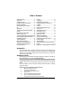
Table of Contents Table of Contents .....................................2 Introduction...............................................2 Included in the Kit .....................................2 Installation Points to Remember...............3 Harness Description .................................4 Flashing the Hood Pin Switch...................9 Tip.............................................................9 Remember:...............................................9 The Programming Assistance Button .....
x 1 – two-pin 22 AWG Harness (Accessories Harness) x 1 – parts bag: a Hood Pin-switch, a Connector and a Warning Label x 1 – User Guide The plug-in Valet button is no longer included with this Remote Car Starter. INDUSTRY CANADA USER NOTICE: Operation is subject to the following two conditions: (1) this device may not cause interference, and (2) this device must accept any interference, including interference that may cause undesired operation of the device.
Ƈ When wiring in parallel, make sure you isolate each connection with a diode in order to avoid feedback and possible damage. Examples: Wiring a Clutch Bypass and a Transponder Module to the GROUND OUT WHEN RUNNING wire: At the junction point, where the GROUND OUT WHEN RUNNING wire “splits” and connects to each device, a diode is inserted on each of these lines.
E ORANGE F GREEN Warning: at the Ignition Switch of certain vehicles, there may be more than one Ignition wire. Use the 5th relay (Pin F) and extra relays to power up any extra Ignition wires if necessary. Do not jump wires at the Ignition Switch: this would compromise the OEM electrical system. This wire will power the Heater Blower Motor. Usually connected to the Accessories wire of the vehicle.
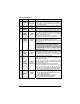
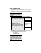
12-Pin Accessories Harness Wire Colour 1 BLUE 2 BROWN 3 GREEN 4 WHITE / BROWN 5 WHITE / GREEN 6 BLUE / WHITE 7 WHITE / ORANGE 8 ORANGE P. 6 Function Description 500 mA negative output. This output can be used to control the (–) Trunk / Trunk release (1-sec. pulse), or it can be set to operate as a AUX 3 output constant output as long as the TRUNK button is held pressed (for Sunroof or Window closure) (–) Lock Programmable 500 mA negative output: 1/10-sec., 7/10-sec. or 4output sec.
9 PURPLE (–) External Trigger 10 WHITE (–) Ground Out When Running 11 GREY (–) N/A AS-2510 TW Installation Guide The External Trigger wire can be used for remote-starting the vehicle with an external device. When the vehicle is running, triggering this input will activate Idle Mode. The External Trigger wire can also be used to operate as a negative trigger with the Trunk Pin-switch, the Key Sense wire or the Door Pin-switch: Option 1 Connects to Negative Trunk Pin.
In Diesel Mode, this positive input will monitor the Glow Plug Light: it will wait for up to 18 seconds until the Glow-plug Light goes out before allowing the Remote Car Starter to proceed to cranking the Engine. Connect to the side of the Glow-plug Light which is positive when the Light is on. Note: the Remote Car Starter will nevertheless proceed to cranking the Engine if the Glow-plug Light is still on after the 18sec. delay (25 sec. when the Run Time is set to 30 min.).
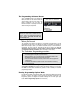
Flashing the Hood Pin Switch Flashing the Hood Pin switch is a procedure that brings the Remote Car Starter into Programming Mode. Once the Remote Car Starter is in Programming Mode, the installer will have up to 20 seconds to select one of the sub-menus. If the installer fails to select a sub-menu before the 20-second delay, the Remote Car Starter will exit Programming Mode and the installer will have to flash the Hood Pin switch once more.
The Programming Assistance Button (A.k.a. the PAB.) Mounted on the Remote Car Starter, this button can be used from within the vehicle instead of the Hood Pin switch in the Engine compartment. This will spare the installer the trouble of accessing the Hood Pin switch in the Engine compartment. Caution The Hood Pin switch must be installed and connected in order for the Programming Assistance Button to function. The button will work only when the Hood is up.
1. Flash the Hood Pin switch (see Table 1) – The Parking Lights will stay ON for up to 20 seconds. – Before the lights go out: 2. Press and hold the Brake Pedal, – And press one of the following buttons on the Transmitter: x LOCK..................to access Mode 1; x UNLOCK..............to access Mode 2; x TRUNK ................to access Mode 3. The Parking Lights will flash and the horn will honk (if configured) once, twice or three times to confirm entry into a Mode. 3. Release the Brake Pedal.
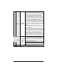
FUNCTION 3 – Passive or Active Arming OPTION 1* OPTION 2 OPTION 3 PASSIVE Arming (60 sec.) ACTIVE Arming PASSIVE Arming (3 min.) FUNCTION 4 – Door lock pulse timing OPTION 1* OPTION 2 OPTION 3 OPTION 4 7/10-sec. Lock/Unlock pulses 4-sec. Lock/Unlock pulses 7/10-sec. Lock pulse and two 1/4-sec. Unlock pulses 1/10-sec. Lock/Unlock pulses FUNCTION 5 – LED flashing OPTION 1* OPTION 2 OPTION 3 MODE 2 ENABLED DISABLED DISABLED * INDICATES DEFAULT SETTING FUNCTION 1 – Safe Start.
FUNCTION 3 – AUX 2 Programming OPTION 1 OPTION 2* OPTION 2 OPTION 4 Constant output while the LOCK and UNLOCK buttons are pressed. In Safe Start Mode: activate AUX 2 by pressing the START button. Toggle ON/OFF (with 30-second timeout) Toggle ON/OFF (with 60-second timeout) Priority Door Access FUNCTION 4 – AUX 1 Programming OPTION 1 OPTION 2* OPTION 3 Horn Confirmation upon the 2nd press of the LOCK button. Priority Door Access Horn Confirmation upon the 1st press of the LOCK button.
Note The L.E.D. follows the Parking Lights during the Transmitter Programming procedure. At any time, close the Hood to end the Tachprogramming procedure. Automatic Tach Programming This simple procedure can replace the Multi-speed Tach Programming procedure: 1. Make sure that all the connections are properly made and that the Remote Car Starter is powered up. 2. With the Hood up (ground on the Hood Pin switch line), start the vehicle using the Key. 3. Allow the vehicle to reach regular Engine idle speed.
installation and operation of the system. Before testing, make sure that all connections are soldered and that the unit is plugged in. Remote-start the Engine and listen for Starter drag. If the Starter cranks for too long, carry out another Tach Programming procedure. Hood Switch shutdown. with the vehicle running under the Remote Car Starter, open the Hood; the vehicle should shut down. If it does not shut down, check the Hood Pinswitch and its connector. Brake shutdown circuit.
Supplementary Information Fifth Relay Output (2nd IGN, ACC or CRANK) Remote Car Starters of this series are equipped with an on-board high-current programmable 5th Relay that can be used to power a second Ignition, Accessory or Crank wire. The Unit uses 3 sets of pins; each set corresponds to a specific function of the output. In order to activate one of the three possible functions, you must place the Jumper (supplied) on one of the three sets of pins and connect the 14 AWG wire to the second IGN. / ACC.
Smart Secure Lock If the vehicle is initially locked, upon remote START the Remote Car Starter will trigger an unlock pulse and a disarm pulse before the Engine is started. The Remote Car Starter will LOCK again when the Engine is running, and LOCK once again 4 seconds after shut-down. If the vehicle is initially unlocked, upon remote START the Remote Car Starter will start the Engine and arm the Starter Kill, but the Doors will not be locked or unlocked at any moment of the sequence.
2. Press and release the Break Pedal 5 times (within 13 seconds from entering Programming Mode). 3. The Parking Lights will flash 8 times to confirm resetting. Table 8: Resetting without a Valet Button On some vehicles (such as BMW and certain Volkswagen vehicles), resetting will not work if the Brake Pedal is pressed while the Ignition Key is not in the IGNITION ON (RUN) position: you will need therefore to hot-wire the Brake Pedal by manually jumping 12 V with a fused test lead at the Brake Pedal switch.
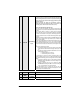
Diagnostics – Parking Light Flash Table Flashes 1 2 3 4 5 6 Description x x x x x x x x x x x x x x x x x 8 10 1 – pause – 2 x x x ON solid x x 2 – pause – 2 ON 2 sec. ON 3 sec. ON 4 sec. ON 25 sec. Irregular Constant flashes up to 30 sec. x x x x x Doors locked, Starter Kill armed. End of Run Time. TRUNK button pressed Start signal received by the Remote Car Starter. Cold Weather Mode cancelled. Cannot start after maximum number of attempts is reached. Doors unlocked, Starter Kill disarmed.