
Installation guide

P. 8 Installation Guide AS-2360TW
Caution! The installer should use either the positive
or the negative Door input. Never use both of them
simultaneously.
It is essential that the Remote Car Starter be
connected in such a way as will allow each one of
the Doors to turn off Ready Mode: the driver-side
Door Pin does not constitute by itself a
sufficient connection.
7
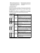
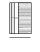
WHITE /
ORANGE
(–
)
Starter Kill
output
(armed
output)
This wire will provide a constant 500 mA output when
the system is armed
(
locked b
y
remote control
)
. It
can be connected to an external starter interrupt
relay. This wire should be connected to a sin
g
le pole
double-throw rela
y
: this wire will connect to pin 85 on
the rela
y
, and pin 86 will be connected to the i
g
nition
wire. The starter kill output becomes active durin
g
remote starts. One benefit of the starter kill is the
anti-
g
rind feature. Once the vehicle has been remote
started, the anti-
g
rind prevents the starter motor from
re-en
g
a
g
in
g
when the i
g
nition ke
y
is inserted in the
ignition switch and accidentally turned to the
CRANK
position.
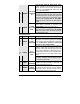
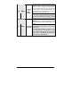
8 ORANGE
(–) Parking
Brake input
Connect to the ne
g
ative Parkin
g
Brake Indicator Li
g
h
t
wire of the vehicle. This wire is found at the parkin
g
brake lever itself.
Note: The wire should test ground when the Parking
Brake is engaged.