
Installation guide

AS-2360TW Installation Guide P. 7
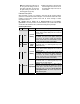
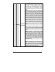
This wire provides a +12 V output and must be
connected on the vehicle to the parkin
g
li
g
hts wire
that tests +12 V when the light switch is in the ON
position.
5 YELLOW
(+) 12 V
Parkin
g
Li
g
ht
output
Note: ensure that the volta
g
e does not decrease or
increase when the dimmer control switch is turned. If
the volta
g
e
g
oes up or down, find another parkin
g
light wire.
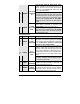
12-Pin Accessories Harness
Wire Colour Function Description
1 BLUE
(–) Trunk /
AUX 3 output
500 mA negative output. This output can be used to
control the trunk release (1-sec. pulse), or it can be
set to operate as a constant output as long as the
TRUNK button is held pressed (for sunroof or window
closure)
2 BROWN
(–) Lock
output
Programmable 500 mA negative output: 1/10-sec.,
7/10-sec. or 4-sec. pulse
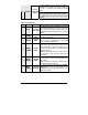
3 GREEN
(–) Unlock
output
Programmable 500 mA negative output: 1/10-sec.,
7/10-sec., 4-sec. or double 1/4-sec. pulse (ON
250 ms, OFF 500 ms, ON 250 ms).
4
WHITE /
BROWN
(–) Rearm
output
500 mA ground si
g
nal when the doors are locked b
y
remote control. This wire will go to ground 1/2 sec.
before the
LOCK pulse, and go out 1/8 sec after LOCK.
The wire must be connected to the OEM arm wire
(usually the door pin).
Note: The module will also give a rearm pulse on
this wire when it shuts down the vehicle after a
remote start.
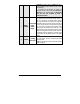
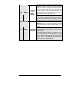
5
WHITE /
GREEN
(–) Disarm
output
500 mA
g
round pulse when the doors are unlocked
b
y
remote control. Connect to the OEM disarm wire
of the vehicle.
Note: The system will also give a disarm pulse on
this wire before every remote start.
6
BLUE /
WHITE
(+) Positive
Door input
This input should be used in vehicles with positive-
switching Door pins or Dome Light circuits.
Connect to the Dome Light wire that tests +12 V
when a Door is open.