
Installation guide

AS-2360TW Installation Guide P. 5
Note: The parking light output relay of
the unit gives two clicking sounds for
each flash of the lights: one click when
the lights would go
ON and one click
when the lights would go
OFF.)
♦ Parking light flashes to which the text
refers throughout this manual refer to
the parking light output of the unit, not
of the vehicle.
Harness Description
When connecting a module, it is important to make sure that the connector with the
ground wire is connected first, before making the 12-volt connections. Should the unit be
powered up before being grounded, there could be serious damage to internal
components of the unit.
Be careful not to power up a module before it is properly
grounded. To avoid any accident, it is recommended to pull out the fuses from their
sockets before the installation, and to put them back during the very last steps.
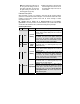
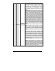
6-Pin Main Ignition Harness
Wire Colour Function Description
Connect to the largest 12 V suppl
y
wire at the i
g
nition
harness. Ensure that the OEM power wire is fused for
more than 30 A.
A RED
(+) 12 V
Battery
Please note: some of the most recent vehicles have
no suitable 12 V source at the i
g
nition switch
(
the
12 V wire is too small to suppl
y
the necessar
y
current
)
. In such cases, it is recommended to use the
fuse box or the B+ connection on the battery.
B PURPLE
(+) Starter
output
(30 A)
Connect to the starter wire of the vehicle. The source
wire should have +12 V with the i
g
nition ke
y
in the
CRANK position only.
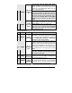
Connect to the largest 12 V suppl
y
wire at the i
g
nition
harness. Ensure that the OEM power wire is fused for
more than 30 A.
C RED
(+) 12 V
Battery
Please note: some of the most recent vehicles have
no suitable 12 V source at the ignition switch
(
the
12 V wire is too small to suppl
y
the necessar
y
current
)
. In such cases, it is recommended to use the
fuse box or the B+ connection on the battery.
Connect to the I
g
nition wire of the vehicle. The source
wire should have +12 V with the i
g
nition ke
y
in the
IGNITION ON (RUN) and CRANK positions.
D YELLOW
(+) Ignition
output (30 A)
Warning: at the i
g
nition switch of certain vehicles,
there ma
y
be more than one i
g
nition wire. Use the
5
th
rela
y
(
Pin F
)
and extra rela
y
s to power up an
y
extra ignition wires if necessary. Do not
j
ump wires
at the Ignition Switch: this would compromise the
OEM electrical system.