
Installation guide

P. 4 Installation Guide AS-2360TW
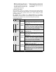
Installation Points to Remember
♦ Make sure that vehicles equipped with
an automatic transmission do not start
while in any of the drive gears. If the
vehicle starts in gear, install a
manual-transmission remote starter
instead.
♦ When installing a manual-transmission
product on a vehicle with a manual
transmission, always make sure that all
doors will get the unit out of ready
mode. switch the wire used so that it is
triggered by all doors.
♦ When installing a manual-transmission
product on a vehicle with a manual
transmission, make sure that the
parking brake and door switch contacts
work properly.
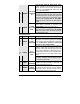
♦ When working on a vehicle, always
leave a window open.
♦ Never leave the keys in the car. Leave
them on a workbench with a window
rolled down.
♦ If possible, remove courtesy light fuse
to prevent battery drain.
♦ The
PROGRAMMING ASSISTANCE BUTTON (PAB)
The PAB is mounted on the side of the
module unit and fulfils the same
function as the hood-pin switch. The
PAB will spare installers the effort of
getting out of the vehicle to access the
hood-pin switch. The PAB works only
when the hood is up.
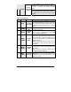
♦ Inspect vehicle for any body damage or
electrical problems
♦ Always solder and tape all connections.
♦ Keep the antenna away from other
types of antennas (GPS/OnStar).
♦ Never install the control unit where it
could interfere with normal operation or
obstruct service technicians.
♦ Always use a grommet when running
wires into the engine compartment.
Never run wires through bare or sharp
metal.
♦ Do not disconnect the battery on
vehicles equipped with air bags and
anti-theft radios.
♦ Never ground the control unit to the
vehicle’s steering column.
♦ Make sure that all the switches and
controls operate properly.
♦ Verify that the vehicle starts and idles
properly.
♦ Make sure that all safety equipment is
installed: the valet button (if provided),
the hood switch and the warning label.
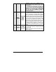
♦ When wiring in parallel, make sure you
isolate each connection with a diode in
order to avoid feedback and possible
damage.
Examples
:
Wiring a clutch bypass and a
transponder module to the ground-out-
when-running wire: At the junction
point, where the ground-out-when-
running wire “splits” and connects to
each device, a diode is inserted on
each of these lines.
Multiple or separate door pin connec-
tions:
When joining all door pins together to
the door pin input wire of the module
unit, each wire must be isolated with a
diode to prevent feedback.
Note: The above examples reflect
common situations where diodes are
use to isolate connections. Please note
that there are numerous other cases
where diode isolation is required.
♦ Always make sure that all external
relays or modules added to the module
unit are properly fused and diode
isolated.
♦ On vehicles equipped with daytime
running lights, the installer may be
unable to see certain programming
results since the daytime running lights
never go out.