
Installation guide

P. 12 Installation Guide AS-2360TW
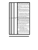
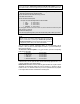
12 YELLOW
(+) Glow-Plu
g
input
(cont.)
• Connecting the glow-plu
g
input wire of the
module to ignition will hold the ignition ON for
the maximum waiting time (15 seconds
recommended)
• Keeping the module’s glow-plu
g
input wire
unconnected will hold the ignition ON for the
minimum waitin
g
time
(
3 sec., not recommended
in very cold environments).
Connect the glow-plu
g
wire to the i
g
nition wire onl
y
after the tach programming has been completed:
connecting the glow-plu
g
wire is one of the ver
y
last
steps in the installation process.
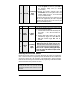
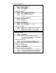
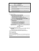
2-Pin Harness
Wire Colour Function Description
1
BLUE/
WHITE
(–) AUX 2
output
This 500 mA negative output can be programmed
for one of the following Options:
1. Constant while the
SHIFT button followed by the
LOCK button, + 1 sec. after the buttons are
released.
2. Pressing
SHIFT button followed by the LOCK
simultaneously toggles the output ON and
OFF with automatic toggle OFF after 30
seconds.
2
YELLO
W
(–) Parking
Light
output
500 mA negative parking light output
Note: Ensure that the voltage does not vary
when the dimmer control switch is turned up or
down. If this is the case, it is not the right wire.
There is also a positive parking light output.
Only one of these two different outputs needs
to be connected.
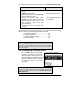
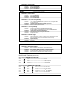
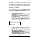
Flashing the Hood-Pin Switch
Flashing the hood-pin switch is a procedure that brings the module into programming
mode. Once the module is in programming mode, the installer will have a maximum of
20 seconds to select one of the sub-menus. If the installer fails to select a sub-menu
before the 20-second delay, the module will exit the programming mode and the installer
will have to flash the hood pin switch once more.
Tip
As long as the hood is up, you may use the
programming assistance button instead of the hood-
pin switch.