
User manual


Chapter 8 Virtual Chip Mode 105
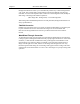
System Connection Diagram:
Computer
110/220
Controller
Detector
EXPERIMENT
110/220
Camera
Detector-Controller
Serial Com
or USB 2.0
Interface cable
(TAXI or USB 2.0)
Microscope
Figure 59. System Diagram
Procedure:
1. Verify that the power is OFF for ALL system components (including the host
computer).
2. Verify that the correct line voltages have been selected and that the correct fuses
have been installed in the ST-133.
3. Connect the TAXI cable to the interface card at the host computer and to the
Serial Com connector at the rear of the Controller. Tighten down the locking
screws.
4. Connect the Camera-Controller cable to the Detector connector on the rear
of the Controller and to the Detector connector at the rear of the camera.
Tighten down the locking screws.
5. If it has not been installed already, connect a line cord from the Power Input
module on the back of the Controller to a suitable AC power source.
6. Turn on the Controller.
7. Turn on the host computer and select the WinView/32 icon.
8. From the Setup menu, select Hardware, and enter the following settings:
Controller/CCD tab card
• Controller: MicroMAX
• Controller Version: 5
• CCD Type: appropriate frame transfer array (EEV 512x512FT, for this
procedure)
• Shutter Type: None
• LOGIC OUT Output: Shutter
• Readout Mode: Frame Transfer