M A N U A L / A U T O M A T I C T R A N S M I S S I O N M U L T I - C H A N N E L R E M O T E S T A R T E R S Y S T E M AS-2272 Installation Guide Notice The manufacturer will accept no responsibility for any electrical damage resulting from improper installation of the product, be that either damage to the vehicle itself or to the unit. This unit must be installed by a certified technician using all safety devices supplied.
Table of Contents Introduction ............................................................ 2 Other Features of the Module............................. 18 Included in the Kit.................................................. 3 Fifth Relay Output (2nd IGN, ACC or CRANK) 18 Installation Tools.................................................... 3 Tach jumper settings......................................... 18 Installation Points to Remember.......................... 3 Clutch Bypass ....................
Included in the Kit Before beginning the installation, please review the Installation Guide —particularly the Wiring Diagram and the Programming Options. Note: It is very important that you familiarize yourself with the programming and operation of the system, even if you have already installed a similar system in the past. There are many great new features you may overlook if you do not read the Guide–you would not maximize the potential of the unit.
♦ When wiring in parallel, make sure to isolate each connection with a diode in order to avoid feedback and possible damage. Examples: Wiring a clutch bypass and a transponder module to the ground out when running wire: At the junction point, where Ground Out when running “splits” and goes to each device, a diode is inserted on each of those lines.
Installation Order The following is a suggested order for the Installation procedure. It is intended as a guide for novices, to help make the process of installing a remote starter module easier. Time is wasted by rewiring the module when mistakes are made. Also, the neatness of the installation is lessened every time the module is taken down and the wiring is “corrected”. A messy installation is harder to trouble shoot if there are problems later on.
when the module is in the vehicle. The fuses on the power wires should be removed during the pre-wire stage. The fuses will not be put back in until the powering stage of the installation. − Once the pre-wiring is finished, the module can be brought into the vehicle. Before the module is mounted, connect the antenna, the valet switch, shock sensor (if applicable) and LED to the module. With everything connected to the module, it can now be mounted in the vehicle. Use tie-straps to secure it to the vehicle.
A basic introduction to the Relay What is a relay? A device that responds to a small current or voltage change by activating switches or other devices in an electric circuit. An electromagnetic switch, remote-controlled switch, a switching device. Why are Relays used? Relays can have several purposes in remote car starter installations. They are used mainly for isolation, inversion, interruption, strengthening current, and for powering multiple wires from one source SAFELY.
quenching/suppression diode, and that the Negative trigger is on the same terminal of the relay as the Anode (+ or non-striped side) of the quenching/ suppression diode. When a relay’s coil is energized, a magnetic field is created and energy is stored in the coil. When power is removed from the coil, the magnetic field collapses. This causes a Reverse Voltage to be generated and can sometimes reach 200 volts. A quenching diode absorbs this reverse voltage spike.
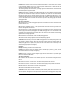
Problem: Some vehicle circuits need to be isolated from feedback. In some cases, when a vehicle is remote started, feedback occurs on a circuit and powers another device or switch that was not intended to be powered during the remote starts. The following example will be a Positive (+) Parking Light circuit that feeds back and activates the windshield wipers during remote starts.
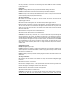
the relay is activated, +12 volts from 87 is sent through 30, and the OEM trunk switch is activated, by the positive pulse. Interruption: Example: Creating a Starter Kill relay to prevent unauthorized starting of the vehicle. Problem: The OEM starter circuit needs to be disabled only when theft is attempted. Solution: A relay is used to interrupt the OEM starter wire. There is an output on the remote start module especially for this purpose (Starter Kill output).
module's Trunk release output activates the relay. The ground signal is sent from 87 through 30 to the vehicle's Trunk release wire activating the switch and opening the trunk. Harness Description 6-pin Main Ignition Harness (a.k.a. The Primary harness) The two Red wires are the power inputs for the module; the other wires are for recreating the actions of the Ignition switch during remote starts. On most vehicles these wires are connected at the vehicle's Ignition switch.
5-pin Secondary Harness (a.k.a. the secondary harness) This harness has the remaining wires used in basic remote starter installations, positive parking light output, the safety shut down inputs, and the ground wire for the module. Wire 1 BLACK (–) Chassis ground input Description This wire must be connected to bare, unpainted metal (the Chassis or true Body ground). (AC) Tachometer input This wire tells the module if the Engine is running or not. It requires at least 1.8 volts (AC) and 1.
VIOLET (+) Door pin input This input should be used in vehicles that use a positive-switching Dome Light circuit. Connect to a Door trigger wire testing +12 V with a Door open. CAUTION! You can only use a negative or a positive connection. In other words, only the NEGATIVE DOOR INPUT or the POSITIVE DOOR INPUT wire is connected.
If no Glow-plug wire is found on the vehicle, the Glow-plug input on the module may be “timed out”. The module will power up the Ignition and Glow-plug circuits and simply wait for the time-out before starting. Keeping the Glow-plug input wire of the module unconnected will hold the ignition ON for the preprogrammed delay. Please program the tach before connecting the glow-plug input to the vehicle.
Note: To exit programming mode, close the hood. Note: To exit programming mode, press on the antenna button once (the LED will come ON) and release. Remember: You can use the programming Assistance button instead of the hood pin at any time the hood is up. The Programming Assistance Button (a.k.a. PAB) The PAB is located on the side of the module. This push button mimics the hood-pin switch in order to avoid having to get out of the vehicle and pressing the hood-pin switch.
To install this unit in a vehicle with an automatic transmission: 1. Cut the loop on the pc board (Yellow wire). 2. Make sure the Black/White handbrake wire is not connected to any of the vehicle circuits. 3. Make all the regular connections. 4. Power up the unit. The parking lights will flash 4 times. 5. When learning the first transmitter, the parking lights will flash 5 times quickly then give 2 slow flashes, confirming that the module is set to automatic mode. 6.
FEATURE 4 – Door lock pulse timing OPTION 1* 7/10-sec. lock / unlock pulses OPTION 2 4-sec. lock / unlock pulses OPTION 3 7/10-sec. lock pulse and two 1/4-sec. unlock pulses FEATURE 5 – LED flashing OPTION 1* ENABLED (without starter kill Æ will flash only when ignition is OFF) OPTION 2 DISABLED OPTION 3 ENABLED (with starter kill Æ will ONLY flash when the starter kill engages. This option should be selected ONLY if the starter kill is installed.
3. Press the Ι button if you wish to increase the time delay or the ΙΙ button if you want to decrease it. The time delay will be increased or decreased by 50ms. and the parking lights will flash once every time the Ι or ΙΙ button is pressed. 4. Press the Ι and ΙΙ buttons together to save the settings you have entered. 5. Release the brake pedal – the time delay programming is now complete. Multi-speed Tach Programming 1.
Clutch Bypass In order to remote start a manual transmission vehicle, the clutch switch must be bypassed. Clutch safety switch circuits can take many forms. Listed below are the most common ones. Some vehicles may also have a separate or combined switch on the clutch pedal for cruise control. Usually a cruise control switch reacts the moment you touch the pedal, whereas a clutch switch reacts only when the pedal is near the floor.
modules connected to the G.O. Wire, a relay (and diodes) may have to be added to strengthen the negative current going to the clutch bypass. Positive: Very similar to the negative system, except that the vehicle's clutch relay is triggered by 12 volts instead of a negative signal. In a Positive system, when the clutch is pressed; a positive (12 volts) signal is sent to the relay.
Starter Kill Arming Mode Note: It can only be activated if button Ι is programmed as LOCK or UNLOCK button. The Starter Kill (if installed) can be configured by the installer either to Passive Mode (so as to arm automatically) or Active Mode (so as to require the user’s intervention for arming). By default, the Remote Car Starter is configured to Passive Mode.
Bypass Remote starters of this series offer three possibilities for bypass D2D: they are compatible with Trilogix, ADS and Fortin bypasses (Trilogix by default). Engine Run Time On a gas engine, the Remote Car Starter can be programmed to run the engine for 3, 15, or 25 minutes (15 minutes by default). On a diesel engine, the Remote Car Starter can be programmed to run the engine for 8, 20, or 30 minutes (20 minutes by default).
To enter Cold Weather Mode: • Press and hold the ΙΙ button for 3 seconds or until the parking lights flash three (3) times. To exit Cold Weather Mode, do any one of the following actions: • Open the hood. • Start the engine by remote. • Start the engine with the key. • Press and hold the ΙΙ button for three seconds (the parking lights will flash once).
c. Press the push button switch until the Parking lights flash twice. d. Release the push button and turn the ignition to the OFF position. The LED on the antenna will flash quickly to indicate that the vehicle is now out of Valet mode. Panic Mode Note: Panic mode can only be activated if the horn option has been adequately installed and programmed by the installer. Button Ι has to be programmed as LOCK and UNLOCK.
transmitter. The parking lights will flash 3 times quickly and remain lit. 4. Remove the key: the engine will continue running. 5. Exit the vehicle and close all doors, hood and trunk. 6. Press for approx. 1 second either button: Ι or ΙΙ. Note: The vehicle will also enter Ready Mode once the engine run time expires. Resetting the module to default features Resetting the module is not a required process.
OEM alarm control. Make sure the module is able to arm and disarm the oem alarm (if applicable). Door locks and trunk testing. Make sure each of these options respond to the transmitter (if installed). Starter kill option. Sit inside the vehicle with all doors closed. Arm the vehicle, then try to start the engine with the key. The engine should not start. If the engine starts, rewire the starter kill to reach proper operation. Valet mode.
Diagnostics – Parking Light Flash Table Flashes 1 2 slow flashes followed by 8 quick flashes 2 3 Slow (automatic transm.) 3 4 5 Fast 6 8 10 1 – pause – 2 ON SOLID for 3 seconds….
Troubleshooting Q & A The following are some common installation-related issues. A problem or symptom is given and then possible solutions and/or suggestions as to areas to verify are enumerated. 1. I cannot program the remote control.
• Do you have the correct OEM disarm wire? • Did you program the disarm wire? 11. The ABS and the CHECK ENGINE light come on in the dash. • Are you missing a second ignition or accessory? 12. The car starts and runs but the heater blower motor does not work. • Incorrect accessory wire. • Does it have more than one accessory? 13. The car starts, the heater works but the air conditioning system does not. • Missing second accessory (common on some Fords). 14.
25. I blow fuses every time I try the remote door locks and I have already installed a relay. • Door locks are reverse polarity, and not positive trigger. 26. I blow fuses every time I try the remote trunk release and I have already installed a relay. • Trunk release is reverse polarity, and not positive trigger. P.