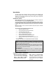
AUTOMATIC TRANSMISSION REMOTE STARTER AS-1820 FM Installation Guide Notice The manufacturer will accept no responsibility for any electrical damage resulting from improper installation of the product, be that either damage to the vehicle itself or to the Unit. This Unit must be installed by a certified technician using all safety devices supplied. Please note that this guide has been written for properly trained technicians: a certain level of skills and knowledge is therefore assumed.
Table of Contents Table of Contents ......................................2 Supplementary Information ..................... 16 Introduction................................................3 Included in the Kit ......................................3 Fifth Relay Output (2nd IGN, ACC or CRANK)................................................... 16 Installation Points to Remember................3 Ignition-controlled Door Locks................. 16 Harness Description ..................................
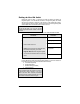
Introduction This Guide contains all the information relevant and necessary for the installation of the Remote Car Starter. Most of the features of this product are explained in the User Guide. Therefore, if you need detailed information about a feature of the product, we recommend that you refer to the User Guide. Included in the Kit Please carefully read the Installation Guide before beginning the installation, especially the Harness Description section and the Programming Options.
Ƈ When installing a manual-transmission product on a vehicle with a manual Transmission, make sure that the Parking Brake and Door Switch contacts work properly. Ƈ When working on a vehicle, always leave a window open. Ƈ Never leave the keys in the car. Leave them on a workbench with a window rolled down. Ƈ If possible, remove courtesy light fuse to prevent battery drain.
Be careful not to power up a Remote Car Starter before it is properly grounded. To avoid any accident, it is recommended to pull out the Fuses from their sockets before the installation, and to put them back during the very last steps.
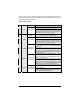
5-Pin Secondary Harness Wire Colour 1 BLACK 2 PURPLE 3 GREY 4 ORANGE 5 YELLOW Function Description This wire must be connected to bare, unpainted metal (the Chassis (–) or the true Body ground). It is preferable to use a factory ground Chassis ground bolt rather than a self-tapping screw. Screws tend to get loose or input rusted over time and can cause erratic problems. This wire will allow the Remote Car Starter to sense whether the Engine is running. The wire requires at least 1.
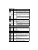
WHITE / ORANGE 8 ORANGE 9 PURPLE 10 WHITE This wire will provide a constant 500 mA output when the system is armed (locked by remote control). It can be connected to an external Starter Interrupt Relay. This wire should be connected to a Single Pole Double-Throw (–) Starter Kill Relay: this wire will connect to Pin 85 on the Relay, and Pin 86 will output be connected to the Ignition wire. (armed output) The Starter Kill output becomes active during remote starts.
11 12 GREY YELLOW (–) N/A (+) Glow-Plug input This pin is not used. Leave it empty. In Diesel Mode, this positive input will monitor the Glow Plug Light: it will wait for up to 18 seconds until the Glow-plug Light goes out before allowing the Remote Car Starter to proceed to cranking the Engine. Connect to the side of the Glow-plug Light which is positive when the Light is on.
Flashing the Hood Pin Switch Flashing the Hood Pin switch is a procedure that brings the Remote Car Starter into Programming Mode. Once the Remote Car Starter is in Programming Mode, the installer will have up to 20 seconds to select one of the sub-menus. If the installer fails to select a sub-menu before the 20-second delay, the Remote Car Starter will exit Programming Mode and the installer will have to flash the Hood Pin switch once more.
The Programming Assistance Button (A.k.a. the PAB.) Mounted on the Remote Car Starter, this button can be used from within the vehicle instead of the Hood Pin switch in the Engine compartment. This will spare the installer the trouble of accessing the Hood Pin switch in the Engine compartment. Caution The Hood Pin switch must be installed and connected in order for the Programming Assistance Button to function. The button will work only when the Hood is up.
2. Press and hold the Brake Pedal, – And press one of the following buttons on the Transmitter: • LOCK..................to access Mode 1; • UNLOCK..............to access Mode 2; • TRUNK ................to access Mode 3. The Parking Lights will flash and the horn will honk once, twice or three times to confirm entry into a Mode (if it has been configured). 3. Release the Brake Pedal.
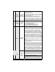
FUNCTION 3 – Passive or Active Arming OPTION 1* OPTION 2 OPTION 3 PASSIVE Arming (60 sec.) ACTIVE Arming PASSIVE Arming (3 min.) FUNCTION 4 – Door lock pulse timing OPTION 1* OPTION 2 OPTION 3 OPTION 4 7/10-sec. Lock/Unlock pulses 4-sec. Lock/Unlock pulses 7/10-sec. Lock pulse and two 1/4-sec. Unlock pulses 1/10-sec. Lock/Unlock pulses FUNCTION 5 – LED flashing OPTION 1* OPTION 2 OPTION 3 ENABLED DISABLED DISABLED MODE 2 * INDICATES DEFAULT SETTING FUNCTION 1 – Safe Start.
FUNCTION 3 – AUX 2 Programming OPTION 1 OPTION 2* OPTION 2 OPTION 4 Constant output while the LOCK and UNLOCK buttons are pressed. In Safe Start Mode: activate AUX 2 by pressing the START button. Toggle ON/OFF (with 30-second timeout) Toggle ON/OFF (with 60-second timeout) Priority Door Access FUNCTION 4 – AUX 1 Programming OPTION 1 OPTION 2* OPTION 3 Horn Confirmation upon the 2nd press of the LOCK button. Priority Door Access Horn Confirmation upon the 1st press of the LOCK button.
Note The L.E.D. follows the Parking Lights during the Transmitter Programming procedure. At any time, close the Hood to end the Tachprogramming procedure. Automatic Tach Programming This simple procedure can replace the Multi-speed Tach Programming procedure: 1. Make sure that all the connections are properly made and that the Remote Car Starter is powered up. 2. With the Hood up (ground on the Hood Pin switch line), start the vehicle using the Key. 3. Allow the vehicle to reach regular Engine idle speed.
Testing Before putting back the vehicle together, it is recommended to check that the system operates properly. The following testing procedures should be used to verify proper installation and operation of the system. Before testing, make sure that all connections are soldered and that the unit is plugged in. Remote-start the Engine and listen for Starter drag. If the Starter cranks for too long, carry out another Tach Programming procedure. Hood Switch shutdown.
Supplementary Information Fifth Relay Output (2nd IGN, ACC or CRANK) Remote Car Starters of this series are equipped with an on-board high-current programmable 5th Relay that can be used to power a second Ignition, Accessory or Crank wire. The Unit uses 3 sets of pins; each set corresponds to a specific function of the output. In order to activate one of the three possible functions, you must place the Jumper (supplied) on one of the three sets of pins and connect the 14 AWG wire to the second IGN. / ACC.
once again). Please note that most OEM systems will not rearm the Alarm while the Engine is running, but will still lock the Doors. Smart Secure Lock If the vehicle is initially locked, upon remote START the Remote Car Starter will trigger an unlock pulse and a disarm pulse before the Engine is started. The Remote Car Starter will LOCK again when the Engine is running, and LOCK once again 4 seconds after shut-down.
1. Flash the Hood Pin switch (see Table 1) – Once inside Programming Mode, you have 13 seconds to complete the next step. 2. Press and release the Break Pedal 6 times (within 13 seconds from entering Programming Mode). 3. The Parking Lights will flash 8 times to confirm resetting.
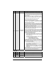
Diagnostics – Chirps Table Chirps 1 2 3 4 5 Constant up to 30 seconds Description • • • • • • • • • • • • Doors locked, Starter Kill armed. LOCK confirmation. Entering Mode 1 in the Programming Centre. Disarmed Notification Doors unlocked, Starter Kill disarmed. Transmitter learnt. Entering Remote Valet. Entering Mode 2 in the Programming Centre. LOCK and arm while a zone is left unprotected. Entering Mode 3 in the Programming Centre. Door Zone left unprotected.
Diagnostics – Parking Light Flash Table Flashes Description 6 • • • • • • • • • • • • • • • 8 10 1 – pause – 2 • • • ON solid • • 1 2 3 4 5 ON 2 sec. ON 3 sec. ON 4 sec. • • • ON 25 sec. • Irregular Constant flashes up to 30 sec. P. 20 Doors locked, Starter Kill armed. End of Run Time. Run Time cancelled. TRUNK button pressed Start signal received by the Remote Car Starter. Cold Weather Mode cancelled. Cannot start after maximum number of attempts is reached.