
User guide

V2.00 SS - Sept, 2009 -
TACH: HIGH
TACH Threshold: NORMAL
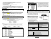
Programming
Assistance Button
(P.A.B.)
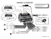
5. Yellow......................(-) parking lights output
4. Black/Brown...........(-) AUX5 output (right sliding door)
3. Black/Green............(-) AUX4 output (left sliding door)
2. White/Purple...........(-) AUX2 output
1. Gray/Blue................(-) External trigger input
5. Yellow...............(-) parking lights
4. Black/Brown....(-) AUX5
3. Black/Green.....(-) AUX4
2. White/Purple....(-) AUX2
1. Gray/Blue.........(-) Ext. trigger
SIDE VIEW OF MODULE
ADS & Fortin
bypass
ADS & Fortin bypass
Xpresskit
bypass
Xpresskit bypass
Yellow Loop
Yellow
Loop
Accessories 2 Jumper
Ignition 2 Jumper
Starter 2 Jumper
Jumpers for 5th relay
(2nd starter, 2nd Ignition,
2nd Accessries)
INV 200
(Door lock pulse inverter)
INV 200
(Door lock pulse
Inverter)
Optional programming
port
Optional
programming
port
REAR VIEW OF MODULE
15 A Fuse
30 A Fuse
30 A Fuse
12- YELLOW .......................... (+) Glow plug input
11- GREY ............................... (
-
) NEG. Door input
10- WHITE .............................. (
-
) GROUND when running
9- PURPLE ............................ (
-
) AUX1output
8- ORANGE ........................... (
-
) Parking Brakes input
7- WHITE/ORANGE ............... (
-
) Starter kill output
6- BLUE/WHITE ..................... (+) POS. Door input
5- WHITE/GREEN .................. (
-
) DISARM output
4- WHITE/BROWN ................. (
-
) REARM output
3- GREEN .............................. (
-
) UNLOCK output
2- BROWN ............................. (
-
) LOCK output
1- BLUE ................................. (
-
) TRUNK output
1- BLACK ........................ GROUND (
-
)
2- PURPLE ........................... TACH (AC)
3- GREY ................. HOOD SWITCH (
-
)
4- ORANGE ........ BRAKE SWITCH (+)
5- YELLOW ....... PARKIN LIGHTS (+)
GREEN ............ 5
th
RELAY
PURPLE ............. STARTER
ORANGE ...ACCESSORIES
(Heater Blower Motor)
YELLOW ........... IGNITION
RED ............+12V (Battery)
RED ..............12V (Battery)
WIRING SCHEMATIC
85
87
(Solenoid Side)
86
30
STARTER WIRE
IGNITION (+)
N/A
Start Kill Output (-)
87A
STARTER WIRE
Optional Starter Kill Relay
For Automatic transmission:
Cut the yellow loop before
plugging the module.