INSTALLATION, OPERATION AND SERVICE MANUAL SERIES 35 SCISSORS LIFT P.O. Box 1058 • 1058 West Industrial Avenue • Guthrie, OK 73044-1058 • 888-811-9876 405-282-5200 • FAX: 405-282-3302 • www.autoquip.com Item #830S35 Version 4.
1. Introduction And Warranty ............................................................................................................. 4 1.1 Introduction .................................................................................................................................... 4 1.1.1 Identification ........................................................................................................................... 4 1.1.2 Inspection ......................................................
6.3.5 Schematics and Field Wiring Details .................................................................................... 33 6.3.6 Troubleshooting .................................................................................................................... 43 7. Parts Lists .....................................................................................................................................
1. INTRODUCTION AND WARRANTY 1.1 Introduction Please read and understand this manual prior to installation or operation of this lift. Failure to do so could lead to property damage and/or serious personal injury. If you have any questions, call a local dealer or Autoquip Corporation at 1-888-811-9876 or 405-282-5200. Please record the following information and refer to it when calling your dealer or Autoquip.
1.2.2 Inspection & Maintenance Lift must be inspected and maintained in accordance with Autoquip’s operating/maintenance (O&M) manual and with other applicable safe operating practices. 1.2.3 Removal From Service Any lift not in safe operating condition such as, but not limited to, excessive leakage, missing parts or fasteners, any bent or cracked structural members, cut or frayed electric, hydraulic, or pneumatic lines, damaged or malfunctioning controls or safety devices, etc.
1.3 Warranty The user is solely responsible for using this equipment in a safe manner and observing all of the safety guidelines provided in the Owner’s Manual and on the warning labels provided with the lift. If you are unable to locate either the manual or the warning labels, please contact Autoquip or access www.autoquip.com for replacement downloads or information.
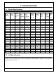
2. SPECIFICATIONS 2.1 Model Specifications Max. End Load Capacity (lbs) Max. Side Load Capacity (lbs) Base and Min. Platform Size (in) Lowered Height (in) Lower Time Fully Loaded (sec.) App. Ship Wt. (lbs.) Model Number Travel (inches) Lifting Capacity (lbs) 24S25 24 2500 2500 2500 24 x 36 6.5 8 4 500 24S40 24 4000 4000 4000 24 x 36 6.5 11 5.5 510 24S60 24 6000 4500 4500 24 x 36 6.
2.3 Load Capacity Load capacity rating is stamped on a metal nameplate attached to lift. This figure is a net capacity rating for a lift furnished with a standard platform. If optional items are installed on lift after leaving manufacturer, deduct weight of these from load rating to obtain net capacity. Do not exceed rated capacity of lift. Loading lift beyond its rated capacity is unsafe, will shorten operational life of lift, and will void warranty. 2.
3. SAFETY 3.1 Safety Signal Words This Owner’s Manual covers Series 35 Lift models produced by Autoquip. Before installing, operating or servicing lift, you must read, understand and follow the instructions and safety warnings in this manual. Your lift may not be equipped with some optional equipment shown in this manual. The safety information in this manual is denoted by the safety alert symbol: ^ The level of risk is indicated by the following signal words.
^ WARNING Prevent serious injury or death. Depending on model, standard weight of lift ranges from 500 – 4700 lbs. Use a properly rated lifting device to move and install lift. 3.3 Operation ^ WARNING Prevent serious injury or death. Scissor lifts are designed for a specific load and application. Do not change load or application from original design. Overloading, or uneven loading, could result in load instability and cause serious personal injury. Stay clear of lift while lift is in motion.
^ WARNING Prevent serious injury or death. Do not attempt to remove Hydraulic Velocity Fuse (HVF) until maintenance device securely supports lift and all hydraulic pressure has been relieved. HVF is attached to elbow fitting in pressure port of cylinder. Do not use a swivel fitting between HVF and cylinder. If HVF is installed improperly, it will not lock up in event of a hydraulic line failure. ^ WARNING Pressurized fluids can penetrate the skin. Hydraulic hoses can fail from age, damage and exposure.
3.6 Modifications ^ WARNING Prevent serious injury or death. Do not modify lift. Autoquip cannot foresee and is not responsible for injury or damage which results from unauthorized modifications or misuse of lift. 3.
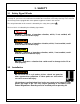
3 – 36402980 4 – 36400661 5 – 36401560 6 – 36401586 13
7 – 36403220 8 – 36403343 ^ WARNING To protect against death or serious injury, all labels must be on lift and must be legible. If any of these labels are missing or cannot be read, call Autoquip for replacement labels.
4. INSTALLATION 4.1 Remote Power Unit Installation 1. The remote power unit is to be located in an area protected from the elements and should be installed prior to the lift to facilitate lift operation during installation into the pit. 2. The remote contractor power unit is equipped with power unit mounting brackets and can be wall or floor mounted using these brackets. If equipped with a vertical power unit, optional power unit mounting brackets must be used for wall mounting. 3.
4.3 Pit Installation ^ WARNING Do not install lift in a pit unless pit has a bevel toe guard or other approved toe protection. A shear point may exist which can cause severe foot injury. Lift platforms traveling below floor levels may create a toe hazard as load passes top edge of pit. This may require guarding in accordance with ANSI MH29.1. Guarding must be installed prior to operating lift. 1. Check pit dimensions.
2 1" CLEARANCE (TYP.) OF PIPE CHASE. FLOOR TO TOP 7" MIN. FROM Series 35 Pit Detail See Pit Installation Notes BASE ASSEMBLY (REF.) 1-3/4" DEEP X 3-1/2" WIDE RECESS FOR CABLES (INTERNAL POWER UNIT), OR HOSE (REMOTE POWER UNIT). 2. RUN 3" DIA. PVC PIPE WITH LONG RADIUS SWEEP ELBOWS TO PROVIDE PIPE CHASE FOR HOSE OR CABLES. RUN FROM PIT OT POWER UNIT OR CONTROL LOCATION. 3. ADD PLATFORM SUPPORT SHELF TO PIT AS SHOWN ABOVE. CURB ANGLES (BY OTHERS). PLATFORM ASSEMBLY IN LOWERED POSITION (REF.).
^ WARNING Prevent serious injury or death. Depending on model, standard weight of lift ranges from 500 – 4700 lbs. Use a properly rated lifting device to move and install lift. 4. Lower lift into pit and check for proper height. Lift must be solid and flush with pit curb angle framing (D). If needed, shim to desired height. DO NOT “spot” shim. Shim along full length of frame. This will prevent frame from sagging under load. 5.
6. Temporarily connect electrical service and hydraulic hoses. The hose connection on the end of the base frame is 1/2" female NPT. Hydraulic Piping/Hose Size Up to 25 feet ½” ID 26 feet to 50 feet ¾” ID Over 50 feet 1” ID 7. Check the routing of the temporary hydraulic lines to assure that the hose is clear of legs, base frame, and platform when lift is in the lowered position. 8. Fill hydraulic reservoir with proper type and volume of fluid. 9. Press “UP button and raise lift one foot. 10.
4.4 Shimming And Anchoring Lift To Concrete Recommended concrete anchor bolts are: HILTI “Kwik-Bolt”, Molly Parabolt or similar. 1. Verify lift is positioned correctly. 2. Drill holes in concrete as specified by anchor bolt manufacturer. 3. Install and tighten anchors as specified by anchor bolt manufacturer. 4. After lift has been aligned, leveled and shimmed, and anchors have been installed, pour grout under entire base frame. 5. When grout has set and cured, tighten nuts on anchor bolts. 6.
Mounting Accordion Skirt Under Platform Raise one side of skirt along with a skirt-mounting bar (1/8" x 1") to underside of platform skirt support bar. When possible, center skirt-mounting collar and skirt-mounting bar (1/8” x 1”) on platform support bar. Align pre-drilled holes in skirt support bar with skirt-mounting bar holes and punch holes in skirt-mounting collar. Push a nylon drive rivet through each hole in skirt-mounting bar. Hammer aluminum pin into rivet until flush with rivet head.
4.6 Toe Indicator Skirt 1. Position the platform in the raised position. Install the maintenance locks (see “Lift Blocking Instructions”). Position the Toe Indicator skirt with the weight rod pocket at the bottom and the Internal Horizontal Velcro strip at the top. See Toe Indicator Drawing. 2. The skirt should be mounted to the platform sides to allow the skirt to extend approximately 8” below the bottom of the platform, see Toe Indicator Drawing.
Toe Indicator Skirt Installation 23 CORNER #2 SIDE C CORNER #3 AT CORNER #3, ON OUTSIDE SURFACE, LOCATE OR CUT 1" SLOT IN TOP OF WEIGHT ROD POCKET. INSERT RODS INTO SLOT, (1) FOR SIDE 'C' AND (1) FOR SIDE 'D' HANGING TOE INDICATOR SKIRT W/ WEIGHT ROD POCKET ON BOTTOM WRAP SKIRT CLOCKWISE AROUND PLATFORM USING VELCRO TO ATTACH TO SIDE OF PLATFORM TOP OF PLATFORM SIDE B SIDE D 8" (TYP) START SKIRT INSTALLATION AT CORNER #1 ON SIDE OF PLATFORM (AS SHOWN) START PLACING SKIRT APPROX.
5. OPERATION 5.1 Raise And Lower Lift ^ WARNING Prevent serious injury or death. Before operating lift, all personnel interacting with lift must read, understand and follow instructions and safety warnings in this manual. NOTICE Adjusting safety relief valve may result in premature motor failure. Do not adjust safety relief valve. Raising loads exceeding rated capacity of lift may result in excessive wear and damage to lift. ^ WARNING Prevent serious injury or death.
6. MAINTENANCE 6.1 Maintenance Device ^ WARNING NEVER go under a raised lift platform until load is removed and lift is securely blocked in raised position with maintenance device. Lock-out/tag-out power source. This procedure describes the only factory-approved method of working under a lift. Follow these instructions EVERY time you plan to reach or crawl beneath the lift to perform service or maintenance – no matter how momentary that might be.
Figure 6.1 Figure 6.2 ^ DANGER If for any reason you are unable to lower the lift completely onto the maintenance devices, stop immediately and consult the factory. Failure to properly use the factory approved maintenance devices could result in severe injury or death. 5.
^ WARNING Failure to relieve operating system pressure could result in the sudden and unexpected release of high-pressure fluids (or air) during maintenance and/or repair of the lift, resulting in severe injury or death. 6. Follow OSHA electrical lock-out/tag-out procedures. Disconnect and tag all electrical and/or other power sources to prevent an unplanned or unexpected actuation of the lift. 7.
^ WARNING Spilled hydraulic fluid is slippery and may also present a fire hazard. Clean up spilled hydraulic fluid. Normally, scissor lifts will require very little maintenance. However, a routine maintenance program could prevent costly replacement of parts and/or downtime. 6.2.1 Every Day Or 10 Hours Of Operation • • • • • • Check reservoir fluid level. Check for fluid leaks. Check all hoses and electrical cords for cracks, abrasions, twisting, etc.
6.2.4 Oil Requirements Follow recommendations below that apply to your application. Environment (Ambient Temperature) Recommended Oil Indoor locations with variable temperatures: 30 100 degrees F. Indoor locations with constant temperatures: 60 - 80 degrees F. 5W 30 or 5W 40 Multiviscosity Motor Oil Outdoor locations: 30 - 120 degrees F. 5W 30 or 5W 40 Multiviscosity Motor Oil Outdoor locations: 10 degrees F below 0 to 100 degrees F.
6.3 General Maintenance 6.3.1 Hydraulic Cylinder Repair 6.3.1.1. Cylinder Plunger Removal 1. Raise lift to its full height and engage maintenance devices. See “Maintenance Devices”. 2. Disconnect electrical power to lift. Follow lock out-tag out procedure. 3. Disconnect cylinder hose at power unit end and insert into reservoir oil-fill hole. 4. Loosen the setscrew or hex bolt in the cylinder upper leg clevis (otherwise known as the Trunnion clevis). 5. Remove the cylinder pin from the upper leg clevis. 6.
6.3.1.3. Placing Cylinder Back Into Service Loctite PST #567 pipe thread sealant or equivalent is recommended. NOTICE Do not use Teflon tape on hydraulic threaded connections. Tape fragments may damage hydraulic system. Autoquip recommends replacing any NPT fittings that have been disassembled due to their inherent design for sealing. 1. Check that lift anchors are tight (when used). Check all pins and other mechanical and hydraulic connections. 2. Restore oil level.
6.3.3 Hydraulic Velocity Fuse (HVF) Replacement ^ WARNING Prevent serious injury or death. Never go under lift platform until load is removed and scissors mechanism is securely blocked in raised position with maintenance devices and hydraulic pressure is relieved. The HVF is attached to elbow fitting in rod port of cylinder. Do not use a swivel fitting between HVF and cylinder. If HVF is installed improperly, it will not lock up in the event of a hydraulic line failure. Velocity fuse is not repairable.
6.3.
Electric Schematic; 115V / 1 Phase / 115V Control 34 OPTIONAL FOOT SWITCH W/ GUARD (NEMA 1) SHIPPED LOOSE WHEN ORDERED. TO BE INSTALLED AND WIRED (BY OTHERS) 3. TYPICAL PILOT CONTROLS ONLY ELECTRICAL SCHEMATIC WIRING DIAGRAM IS LOCATED ON INSIDE OF FRONT COVER. (RED) (GRN) (WHEN USED) (BLACK) L3 (GRN.) (BLACK) (WHITE) "UP" LIMIT SWITCH (XF) 2. PUSH BUTTON (WHITE) 1 AMP FUSE MOTOR STARTER, OVERLOADS,AND FUSES TO BE MOUNTED IN NEMA 1 ENCLOSURE, AND INTERNALLY PRE-WIRED. L1 1.
Electric Schematic; 230V / 1 Phase / 24V Control 35 TYPICAL PILOT CONTROLS ONLY ELECTRICAL SCHEMATIC OPTIONAL FOOTSWITCH W/ GUARD (NEMA 1) SHIPPED LOOSE WHEN ORDERED. TO BE INSTALLED AND WIRED (BY OTHERS) 3. (WHEN USED) L3 (GRN.) (BLACK) (WHITE) "UP" LIMIT SWITCH TRANSFORMER PRIMARY CONNECTION DIAGRAMS ARE LOCATED ON INSIDE OF FRONT COVER. (GRN) 6 4 (XF) 2. PUSHBUTTON 2 2.
Electric Schematic; 208-230-460V / 3 Phase 36 (WHT) (WHT) (RED) FOOTSWITCH IS SHIPPED LOOSE FOR INSTALLATION BY OTHERS (WHEN ORDERED). 3. TYPICAL PILOT CONTROLS ONLY ELECTRICAL SCHEMATIC TRANSFORMER PRIMARY CONNECTION DIAGRAMS ARE LOCATED ON INSIDE OF FRONT COVER. 2. (WHEN USED) MOTOR STARTER, CONTROL TRANSFORMER, HEATERS, AND FUSES TO BE MOUNTED IN NEMA 1 ENCLOSURE, AND PRE-WIRED TO POWER UNIT. (GRN) L1 5 4 115VAC-(RED) 3 (A2) DN. SOL. (WHITE)-115VAC 3 (BLUE)-24VAC O.L.
W 37 GRN UP K BL 3. USE APPROPRIATE WIRE, CONDUIT, ETC. TO SATISFY LOCAL CODES. (BY OTHERS.) 2. COLOR CODING SHOWN CORRESPONDS TO EXISTING 16/4 SO CONTROL CORD ON LIFT. 1. WARNING: ELECTRICAL HAZARD DISCONNECT POWER BEFORE WIRING THIS ACCESSORY.
Optional Guarded Foot Switch Wiring Diagram 38 UP DOWN STANDARD FOOTSWITCH ASSEMBLY 1 2 FOOT GUARD PAINTED YELLOW 9. INSTALL FOOTSWITCH GUARD PER MANUFACTURER'S INSTRUCTIONS. 6. ELECTRICAL RATING WITHOUT CORD 15 AMP, 115/230VAC USE APPROPRIATE WIRE, CONDUIT, ETC. TO SATISFY LOCAL CODES (BY OTHERS). 5. 8. EXCHANGE BLACK AND RED WIRES IF DESIRED TO SWITCH "UP" AND "DOWN" FUNCTIONS. 4. INSTALLER TO APPLY "UP" AND "DOWN" LABELS TO TOP OF COVER AS REQUIRED.
Guarded Foot Switch Assembly 39 NON-SKID BASEPAD BARRIER COMES STANDARD. CAN COME WITHOUT BARRIER AT CUSTOMER'S REQUEST. ALL STEEL CONSTRUCTION COMMON WIRING CHANNEL 5.75" 4.83" 10.
Optional Limit Switch Wiring Diagram SIDE VIEW, BASE DRILLING DETAIL C L 2" BASE ROLLER W/ PLATFORM AT DESIRED ELEVATION C L 1/2" STANDARD END MOUNT TOP VIEW BASE ROLLER (REF.) ORIENTATION SEE DETAIL @ UPPER LEFT ELEC.BOX (INTERNAL P/U) CONTROL CABLE WIRING DETAIL TO BE USED IN MOST CASES UNLESS INTERFERENCE BETWEEN LEG STIFFENER BAR AND LIMIT SWITCH ROLLER WHICH OCCURS IN THE COLLAPSED POSITION.
SIDE VIEW, BASE DRILLING DETAIL Optional Limit Switch Wiring Diagram, Continued 1/2" 2" W/ PLATFORM AT DESIRED ELEVATION C L BASE ROLLER TOP VIEW TYP. (2) HOLES 7/32 DIA. HOLE OPTIONAL TOP MOUNT VIEW "A-A" C L BASE ROLLER (REF.) SEE DETAIL @ UPPER LEFT ORIENTATION 3 4 CONTROL CABLE WIRING DETAIL N.C. LIMIT SWITCH ELECTRICAL BOX STARTER TERMINAL A1 USED ONLY WHEN INTERFERENCE OCCURS ON STANDARD END MOUNT STYLE, EXPLAINED ON PAGE 1. OPTIONAL TOP MOUNT 3.
Hydraulic Schematic (Standard & Contractor PU) 42 SUCTION LINE FILTER RESERVOIR RELIEF VALVE CHECK VALVE DOWN SOL. VALVE 2 DOWN FLOW CONTROL VALVE 1 HYDRAULIC SCHEMATIC PRESSURE LINE AND DOWN SOLENOID VALVE. PUMP ASSEMBLY PROVIDES COMPLETE THE FUNCTION OF: CHECK, RELIEF, VELOCITY FUSES (QTY. DEPENDS ON MODEL) (1) PER CYLINDER. 2 2 1 1 LIFT CYLINDER(S) (QTY.
6.3.6 Troubleshooting WARNING Prevent serious injury or death. Disconnect and/or lock out electrical supply to power unit prior to any maintenance being performed. ^ WARNING Prevent serious injury or death. Never go under lift platform until load is removed and scissors mechanism is securely blocked in open position. Follow OSHA lock-out/tag-out procedure. See "Maintenance Devices" section. ^ WARNING Pressurized fluids can penetrate the skin. Hydraulic hoses can fail from age, damage and exposure.
PROBLEM Lift Raises, Slowly. Then Lowers POSSIBLE CAUSE AND SOLUTION Down solenoid may not be seating. Remove solenoid coil and check. If lift does not hold with solenoid coil removed, remove and clean down valve cartridge or replaced as necessary. Oil line, hose, or fitting may be leaking. Check and repair if necessary. Lift Lowers Slowly. Check valve in pump assembly may not be seating. This is indicated by pump shaft and motor turning backward on their own with no power applied.
PROBLEM Lift Does Not Raise, Continued. POSSIBLE CAUSE AND SOLUTION Breather holes in reservoir fill plug may be clogged. Remove and clean. Voltage may be too low to run pump with existing load. Check by measuring voltage at motor terminals, or as near as possible, while pump is running under load. Inadequate or incorrect wiring can starve motor when source voltage is ample. Correct as necessary. Down valve may be energized by faulty wiring or stuck open. Remove solenoid and check.
PROBLEM Lift Seems Bouncy During Operation. Motor Labors Or Heats Excessively. POSSIBLE CAUSE AND SOLUTION Lower lift to closed position and continue to hold “DOWN” button an additional 10-30 seconds to bleed air from cylinder. Do not confuse spongy or jerky operation with small surges that may occur when operating on rough or uneven floors. Check for oil starvation. Voltage may be low. Check voltage at motor terminals while pump is running under load, not at line source or while pump is idling.
7.
Standard Lift, Continued 48
Series 35 Power Unit 49
Contractor Power Unit 50
5HP / 208-230-460V / 3 Phase Contractor PU 51 WHT. PUSHBUTTON 2 2 2 L3 L2 L1 6 4 GRN. RED BLK. 4 JUMPER L1 6 AUX. CONTACT 5 5 "UP" LIMIT SWITCH (WHEN USED) SECONDARY FUSE PRIMARY FUSE(S) FUSED DISCONNECT (BY OTHERS) 6 TRANSFORMER 6 AUX. CONTACT + - 7 8 3 DN. SOL. (BY AUTOQUIP) BLU. 9 AUDIBLE SIGNAL (WHEN USED) 3 6 FLASHING RED LIGHT (WHEN USED) 9 3 ORG. CONTACTOR COIL O.L.
Air Requirement: 90 PSI & 110 CFM Series 35 Air Power Unit (P/N 64306710) 52
Contractor Air Power Unit (P/N 64306700) 53
Standard & Contractor Air Power Units 54 90 P.S.I 110 C.F.M (MIN. FREE AIR) REQUIRED FILTERED AIR SUPPLY EXHAUST TO ATMOSPHERE REGULATOR (BY OTHERS). P A B AIR CONTROL VALVE (GENERIC VALVE LUBRICATOR AIR HOSE AIR LIMIT VALVE (WHEN USED) AIR HOSE. SUCTION LINE FILTER MOTOR PUMP MUFFLER DOWN VALVE AIR OPERATED AIR / HYDRAULIC SCHEMATIC RESERVOIR RELIEF VALVE CHECK VALVE HYDRAULIC VALVE PROVIDES COMPLETE, THE FUNCTION OF CHECK VALVE, RELIEF VALVE, AIR OPERATED DOWN VALVE. PRESSURE HOSE.
Air Valve Hose Diagram for Air Power Unit 55
Continuous Running Vertical Power Unit 56 L3 L2 L1 2 2 5 4 "OFF-ON PB" MAINT'D CONTACT 2 MS CONTACT 2 FUSE 5 5 FUSE (BY OTHERS) FUSED DISCONNECT (BY OTHERS) 5 8 6 "DOWN" P.B. "UP" P.B. L1 L2 6 5 JUMPER T3 T2 T1 7 7 3 M 3 3 DN. SOL. (BY AUTOQUIP) 8 3 3 3 MOTOR: (BY AUTOQUIP) UP SOL. (BY AUTOQUIP) MOTOR STARTER O.L. CC HEATER O.L. "UP" LIMIT SWITCH (WHEN USED) 3 XFMR. CONTACTS M.S. MOTOR STARTER P.B. = PUSHBUTTON SOL.
Continuous Running Vertical Unit 57 M P.F. 2 1 UP SOL. VALVE DOWN SPEED RESTRICTOR DOWN VALVE WITH PRESSURE COMPENSATED FLOW CONTROL. RETURN LINE FILTER SUCTION LINE FILTER IS INTERNAL TO DELTATROL BLOCK UNLESS A SEPERATE FILTER IS SPECIFIED. RESERVOIR SUCTION LINE FILTER RELIEF VALVE CHECK VALVE DELTATROL VALVE PROVIDES THE COMPLETE FUNCTION OF CHECK, RELIEF, PRESSURE COMPENSATED FLOW CONTROL, SOLENOID LOWERING VALVE AND PRESSURE LINE FILTRATION.
Continuous Running Vertical Power Unit 58