INSTALLATION, OPERATION AND SERVICE MANUAL SERIES 35 “ROVER” 12VDC PORTABLE LIFT P.O. Box 1058 1058 West Industrial Avenue Guthrie, OK 73044-1058 405-282-5200 FAX: 405-282-8105 www.autoquip.com Item #830SRV Version 2.
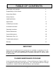
TABLE OF CONTENTS Identification and Inspection 3 Responsibility of Users/Owners 4 Safety Signal Words 5 Safety Practices 6 Label Identification 9 Specifications 13 Lift Blocking Instructions 14 Installation Instructions 17 Operating Instructions 22 Routine Maintenance 23 General Maintenance 25 Replacement Parts List 35 Troubleshooting Analysis 37 Warranty 41 IMPORTANT Please read and understand this manual prior to installation or operation of this lift.
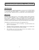
IDENTIFICATION & INSPECTION IDENTIFICATION When ordering parts or requesting information or service on this lift, PLEASE REFER TO THE MODEL AND SERIAL NUMBER. This information is on a nameplate attached to the leg assembly. Replacement parts are available from a local Autoquip distributor. INSPECTION Immediately upon receipt of the lift, a visual inspection should be made to determine that it has not been damaged in transit. Any damage found must be noted on the delivery receipt.
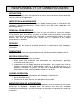
RESPONSIBILTY OF OWNERS/USERS DEFLECTION It is the responsibility of the user/purchaser to advise the manufacturer where deflection may be critical to the application. INSPECTION & MAINTENANCE The lift shall be inspected & maintained in proper working order in accordance with Autoquip’s operating/maintenance (O&M) manual and with other applicable safe operating practices.
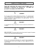
SAFETY SIGNAL WORDS SAFETY ALERTS (Required Reading!) The following SAFETY ALERTS are intended to create awareness of owners, operators, and maintenance personnel of the potential safety hazards and the steps that must be taken to avoid accidents. These same alerts are inserted throughout this manual to identify specific hazards that may endanger uninformed personnel. Identification of every conceivable hazardous situation is impossible.
SAFETY PRACTICES Read and understand this manual and all labels prior to operating or servicing the scissors lift. All labels are provided in accordance with ANSI Z535.4. DANGER! Do not work under lift without Maintenance Device! To avoid personal injury, NEVER go under the lift platform until the load is removed and the scissors mechanism is securely blocked in the open position. See "Lift Blocking Instructions" section.
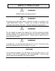
SAFETY PRACTICES WARNING! NEVER stand, sit or ride on the lift! WARNING! All warning and information decals should be in place as outlined in the “Label Identification” section. If decals are missing or damaged, they should be replaced with new ones. Contact Autoquip for replacements. WARNING! Do not attempt to remove the velocity fuse until the maintenance block securely supports the lift and all hydraulic pressure has been removed from the lifting cylinders and hydraulic hoses.
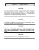
SAFETY PRACTICES CAUTION! Never run the pump for more than a couple of seconds without pumping oil. This applies to low oil conditions, improper motor rotation, running the pump against the relief pressure after the lift is fully raised against the physical stops, running overloaded beyond capacity, or running at reduced speed because of pinched or obstructed hydraulic lines. CAUTION! Do not operate the power unit on relief for more than a few seconds. When on relief, the valve will make a squealing sound.
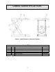
LABEL IDENTIFICATION Figure 1 Label Placement - Oversized Platform Series 35 Rover Item No. 1 2 3 4 5 6 Qty 2 4 1 1 2 2 Description Caution – Familiarize Yourself With Operators Manual Danger – Do Not Put Hands or Feet . . . Autoquip Serial Number Nameplate Fill with Recommended Oils Only Series 35 Label Capacity 9 Part No.
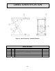
LABEL IDENTIFICATION Figure 2 Label Placement - Standard Platform Series 35 Rover Item No. 1 2 3 4 5 6 Qty 2 2 1 1 2 2 Description Caution – Familiarize Yourself With Operators Manual Danger – Do Not Put Hands or Feet . . . Autoquip Serial Number Nameplate Fill with Recommended Oils Only Series 35 Label Capacity 10 Part No.
LABEL IDENTIFICATION Note: Labels shown here are not actual size.
LABEL IDENTIFICATION Figure 6 Label 36400661 Figure 7 Label 36402980 Figure 8 Label 36401586 12
SPECIFICATIONS Series 35 Model Capacity (lbs) Travel (In.
LIFT BLOCKING INSTRUCTIONS WARNING ! Only authorized personnel should perform inspection or maintenance and service procedures. Unauthorized personnel attempting these procedures do so at the risk of personal injury or death. DANGER ! Failure to properly adhere to lift blocking procedures is to risk the sudden and uncontrolled descent of the lift during maintenance or inspection. A falling lift can cause severe injury or death.
LIFT BLOCKING INSTRUCTIONS Figure 9 Maintenance Locks 15
LIFT BLOCKING INSTRUCTIONS DANGER ! If for any reason you are unable to lower the lift completely onto the maintenance device(s), stop immediately and consult the factory. Failure to properly use the factory approved maintenance device(s) could result in severe injury or death. 5.
INSTALLATION INSTRUCTIONS OIL The Rover is shipped with oil in the power unit. There is no need to fill it. STANDARD DC UNIT WARNING! Read and understand all of the instructions carefully before proceeding with the installation process. 1. The area where the Rover is to be used must be level, solid, and smooth. The unit should roll around freely without obstruction. DANGER! To avoid personal injury, NEVER use the unit in or around water or where flammable gasses may be present. 2.
INSTALLATION INSTRUCTIONS OPTIONAL 115/60 AC UNIT WARNING! Read and understand all of the instructions carefully before proceeding with the installation process. 1. The area where the Rover is to be used must be level, solid, and smooth. The unit should roll around freely without obstruction. DANGER! To avoid personal injury, NEVER use the unit in or around water or where flammable gasses may be present. 2. Remove the material the lift was shipped in.
INSTALLATION INSTRUCTIONS OPTIONAL AIR POWER UNIT UNIT WARNING! Read and understand all of the instructions carefully before proceeding with the installation process. 1. The area where the Rover is to be used must be level, solid, and smooth. The unit should roll around freely without obstruction. DANGER! To avoid personal injury, NEVER use the unit in or around water or where flammable gasses may be present. 2. Remove the material the lift was shipped in.
INSTALLATION INSTRUCTIONS PROCEDURE FOR A LIFT ORDERED WITH AN ACCORDION SKIRT 1. Position the platform in the raised position. Install the maintenance locks (see “Lift Blocking Instructions” section). Position the accordion with the weight rod pocket at the bottom and the mounting collar at the top. The breathable material when provided must be positioned at the top of the skirt with the mounting collar. 2. Slip the skirt over the end of the platform.
INSTALLATION INSTRUCTIONS Figure 10 Skirt Installation 21
OPERATING INSTRUCTIONS 1. Operate this lift only on a firm, flat & level surface. 2. Place the lift in loading position and lock the floor lock when not being transported. 3. Scissors lifts have maximum lifting capacity ratings (See the “Specifications” section). The safety relief valve has been factory set to open at a point slightly above the rated load and allows the oil to bypass into the reservoir.
ROUTINE MAINTENANCE WARNING! Before installing lift, read & follow the recommended safety practices in the Safety Practices section. Failure to follow these safety practices could result in death or serious injury. Normally scissors lifts will require very little maintenance. However, a routine maintenance program could prevent costly replacement of parts and/or downtime.
ROUTINE MAINTENANCE Oil Viscosity Recommendations Environment Recommended Oil (Ambient Temperatures) Indoor location, variable 10W30 or 10W40 temperatures (30 - 100° F) Multiviscosity motor oil Indoor location, consistent SAE-20W motor oil Temperatures (70° F) Outdoor location, (-10 - 100° F) SAE 5W30 Multiviscosity motor oil Cold-storage warehouse 5W30 Multiviscosity (10 - 40° F) motor oil Freezer (-40° F to 0° F) Consult Factory OIL CAPACITY Standard polyethylene tank capacity is approximately five quart
GENERAL MAINTENANCE WARNING! Before installing lift, read & follow the recommended safety practices in the Safety Practices section. Failure to follow these safety practices could result in death or serious injury. CYLINDER REMOVAL AND REPACKING 1. Raise the lift to its full height and block securely. See “Lift Blocking Instructions”. 2. Cut off the electricity to the power unit (lock out-tag out). 3. Disconnect the cylinder hose at the power unit end and insert it into the oil-fill hole of reservoir.
GENERAL MAINTENANCE 14. Check the piston head nut for tightness and torque to 600-650 ft. lbs on 3 ½” bore cylinders or 850-950 ft. lbs. on 4” bore cylinders. The upper clevis and pin may be used to prevent the rotation of the rod while tightening. 15. Liberally lubricate the piston and seal with CLEAN grease or oil. 16. Reinsert the piston into the barrel, taking care not to pinch or nick the new seal. 17. Slip the bearing assembly into place and align the retainer hole with the slot in the barrel.
GENERAL MAINTENANCE VELOCITY FUSE REPLACEMENT DANGER! Do not attempt to remove the velocity fuse until the lift is securely supported with the maintenance locking devices and all hydraulic pressure has been removed from the lifting cylinders and hydraulic hoses. Failure to follow these instructions could result in personal injury or death! Never attempt to take a velocity fuse apart and repair it. These are precision devices that are factory assembled under exacting conditions.
M 28 SUCTION LINE FILTER P.F. RESERVOIR RELIEF VALVE CHECK VALVE DOWN SOL. VALVE PUMP ASSEMBLY PROVIDES THE FUNCTIONS OF CHECK, RELIEF, AND SOLENOID LOWERING VALVE.
GENERAL MAINTENANCE WIRING AUTOQUIP "SUPER TORQUE' MOTORS Because Autoquip "Super-Torque" motors actually deliver substantially more horsepower than their nameplate rating, they must always be wired for heavier currentdraw than standard motors of the same nameplate rating. However, because of the "Super-Torque" motor’s starting efficiency and superior running characteristics, circuit components do not have to be as large as for standard motors of equal delivered horsepower.
PUMP / MOTOR ASSEMBLY DOWN SOLENOID M UP DOWN + - DC MOTOR GENERAL MAINTENANCE Figure 12 Electric Schematic; 12VDC 30
90 P.S.I 110 C.F.M (MIN. FREE AIR) REQUIRED FILTERED AIR SUPPLY Figure 13 Air Schematic EXHAUST TO ATMOSPHERE REGULATOR (BY OTHERS). P A B AIR CONTROL VALVE (GENERIC VALVE LUBRICATOR AIR HOSE AIR LIMIT VALVE (WHEN USED) AIR HOSE. SUCTION LINE FILTER MOTOR PUMP MUFFLER DOWN VALVE AIR OPERATED AIR / HYDRAULIC SCHEMATIC RESERVOIR RELIEF VALVE CHECK VALVE HYDRAULIC VALVE PROVIDES COMPLETE, THE FUNCTION OF CHECK VALVE, RELIEF VALVE, AIR OPERATED DOWN VALVE. PRESSURE HOSE.
Figure 14 Electric Schematic; 115V/1Ph 32 OPTIONAL FOOTSWITCH W/ GUARD (NEMA 1) SHIPPED LOOSE WHEN ORDERED. TO BE INSTALLED AND WIRED (BY OTHERS) 3. TYPICAL PILOT CONTROLS ONLY ELECTRICAL SCHEMATIC TRANSFORMER PRIMARY CONNECTION DIAGRAMS ARE LOCATED ON INSIDE OF FRONT COVER. (RED) (GRN) L1 (WHEN USED) (BLACK) (GRN.) (WHITE) (BLACK) "UP" LIMIT SWITCH (XF) 2. PUSHBUTTON (WHITE) 2.
GENERAL MAINTENANCE Figure 15 Guarded Footswitch Assembly 33
GENERAL MAINTENANCE Figure 16 Limit Switch Wiring Diagram 34
REPLACEMENT PARTS LIST PART # DESCRIPTION 20046320 20046314 20079430 22688154 MECHANICAL Swivel Caster with 5” Dia. Wheel Rigid Caster with 5” Dia.
REPLACEMENT PARTS LIST PART # DESCRIPTION POWER UNITS - AC 20001137 32701290 35105130 41050139 41501776 30000020 Tongue & Groove Coupling Down Solenoid Coil, 24 VAC Pump, 1.
TROUBLESHOOTING ANALYSIS DANGER! To avoid personal injury, NEVER go under the lift platform until the load is removed and the scissors mechanism is securely blocked in the open position. See "Lift Blocking Instructions" section. PROBLEM Lift raises, then lowers back slowly. POSSIBLE CAUSE AND SOLUTION The "Down" solenoid may not be seating. Remove the solenoid coil and check again.
TROUBLESHOOTING ANALYSIS PROBLEM POSSIBLE CAUSE AND SOLUTION Lift does not raise. The battery may not be charged. Charge battery. Check for a line or hose leak. Check for oil shortage in the reservoir. Add oil as necessary (See Oil Requirements in the “Routine Maintenance” section.) The load may exceed the rating. (See the “Specifications” section.) Remove the excess load. The suction screen may be clogged, starving the pump. Remove and clean the screen. Drain and replace the oil.
TROUBLESHOOTING ANALYSIS PROBLEM Lift won’t lower. POSSIBLE CAUSE AND SOLUTION The solenoid coil may be incorrectly wired, burned out, not rated for the voltage, or the line voltage may be excessively low. Check voltage near the coil. The velocity fuse may be locked. Do not attempt to remove the velocity fuse. The following steps should be followed: 1. Remove the load from the lift. Inspect all fittings, hoses, and other hydraulic components for leads or damage. 2.
TROUBLESHOOTING ANALYSIS PROBLEM Lift seems bouncy during operation. Motor labors or heats excessively. POSSIBLE CAUSE AND SOLUTION Battery connections connections. Lower the lift to collapsed position and continue to hold “DOWN” button an additional 10-30 seconds to bleed air from the cylinder. Do not confuse spongy or jerky operation with small surges that may occur when operating on rough or uneven floors Check for oil starvation. The voltage may be low.
LIMITED WARRANTY The user is solely responsible for using this equipment in a safe manner and observing all of the safety guidelines provided in the Owner’s Manual and on the warning labels provided with the lift. If you are unable to locate either the manual or the warning labels, please contact Autoquip or access www.autoquip.com for replacement downloads or information.