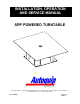
INSTALLATION, OPERATION AND SERVICE MANUAL SRP POWERED TURNTABLE P.O. Box 1058 • 1058 West Industrial Avenue • Guthrie, OK 73044-1058 • 405-282-5200 • FAX: 405-282-8105 • www.autoquip.com Item # 830SRP Version 1.
TABLE OF CONTENTS Inspection 3 Dangers, Warnings, and Cautions 4 Label Identification 7 Specifications 10 Installation Instructions 11 Operating Instructions 15 Routine Maintenance 16 General Maintenance 17 Replacement Parts List 18 Troubleshooting Analysis 19 IMPORTANT Please read and understand this manual prior to installation or operation of this turntable. Failure to do so could lead to property damage and/or serious personal injury.
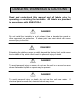
INSPECTION Immediately upon receipt of the turntable, a visual inspection should be made to determine that it has not been damaged in transit. Any damage found must be noted on the delivery receipt. In addition to this preliminary inspection, the turntable should be carefully inspected for concealed damage. Any concealed damage found that was not noted on the delivery receipt should be reported in writing to the delivering carrier within 48 hours.
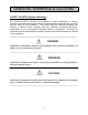
DANGERS, WARNINGS & CAUTIONS SAFETY ALERTS (Required Reading!) The following SAFETY ALERTS are intended to create awareness of owners, operators, and maintenance personnel of the potential safety hazards and the steps that must be taken to avoid accidents. These same alerts are inserted throughout this manual to identify specific hazards that may endanger uninformed personnel. Identification of every conceivable hazardous situation is impossible.
DANGERS, WARNINGS & CAUTIONS Read and understand this manual and all labels prior to operating or servicing the turntable. All labels are provided in accordance with ANSI Z535.4. DANGER! Do not install the turntable in a pit unless it has a beveled-toe guard or other approved toe protection. A shear point can exist which can cause severe injury to the foot.
DANGERS, WARNINGS & CAUTIONS DANGER! To avoid personal injury, stand clear of the unit when the platform is in motion. DANGER! HIGH VOLTAGE!! Disconnect and/or lock out the electrical supply to the power unit prior to any maintenance being performed. WARNING! NEVER stand, sit or ride on the turntable! WARNING! All warning and information decals should be in place as outlined in the “Label Identification” section. If decals are missing or damaged, they should be replaced with new ones.
DANGERS, WARNINGS & CAUTIONS WARNING! Load the platform top as evenly as possible to prevent overloading. Do not load the lift in excess of its rated capacity. CAUTION! Familiarize yourself with the operator’s manual before operating this equipment. CAUTION! Do not continue to depress the “CW” or “CCW switch if the platform does not turn or if the platform is jammed. To do so may result in permanent damage to the motor or speed reducer.
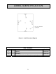
LABEL IDENTIFICATION Figure 1 Label Placement Diagram SRP Turntable Item No. Qty Description 1 2 Capacity 36401586 2 2 No Riders 36403706 3 1 Autoquip Serial Number Plate (when required) 36401511 8 Part No.
LABEL IDENTIFICATION Note: Labels shown here are not actual size.
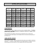
SPECIFICATIONS Model # Lifting Platform Base Capacity Dimensions Dimensions Lowered Shipping Height Weight SRP-3625 2,500 36 x 36 24 x 24 10 385 SRP-3640 4,000 36 x 36 24 x 24 10 385 SRP-3660 6,000 36 x 36 24 x 24 10 385 SRP-4225 2,500 42 x 42 24 x 24 10 450 SRP-4240 4,000 42 x 42 24 x 24 10 450 SRP-4260 6,000 42 x 42 24 x 24 10 450 SRP-4248-25 2,500 42 x 48 24 x 24 10 485 SRP-4248-40 4,000 42 x 48 24 x 24 10 485 SRP-4248-60 6,000 42 x 48 24 x 24 10
INSTALLATION INSTRUCTIONS FLOOR INSTALLATION 1. Make sure installation area is clean before starting. 2. If the permanent electrical work is not complete, some means of temporary lines with an on-off device for the power supply should be set up for testing purposes. 3. Place the turntable in the installation area. CAUTION! When moving the turntable, do not attempt to pick it up by the platform; it is attached in the center only and could be damaged.
INSTALLATION INSTRUCTIONS 6. The base plate of the turntable has pre-drilled holes for lagging it securely to the floor. Mark the holes, drill, and install with anchors. Turntables with oversize platforms have minimum pull out requirements of 2,000 lbs. for each anchor. 7. Make permanent electrical connections and operate the turntable through a few cycles. PIT INSTALLATION -- MODELS WITH BEVEL TOE GUARDS.
INSTALLATION INSTRUCTIONS DANGER! HIGH VOLTAGE!! Disconnect and/or lock out the electrical supply to the power unit prior to any maintenance being performed. 5. The base frame of the turntable has pre-drilled holes for lagging it securely to the floor. Mark hoes, drill, and install with anchors. Turntables with oversize platforms have minimum pull out requirements of 2,000 lbs. for each anchor. 6. Make the permanent electrical connections and operate the turntable through a few cycles.
INSTALLATION INSTRUCTIONS WARNING! The turntable base MUST be attached securely to the lift platform before operating the turntable. 6. If the combination is installed in a pit, see the “Pit Installation” instructions in this section. NOTE: Turntables that have platform sizes larger than the lifts to which they are attached must have toe protection, such as beveled-toe guards 7.
OPERATING INSTRUCTIONS Familiarize yourself with this operator’s manual before operating this equipment. WARNING! NEVER stand, sit or ride on the turntable! 1. Press the “CW” button to cause a clockwise rotation of the turntable. When the “CW” button is pressed, the coil of the motor starter will close the line contact permitting electrical power to be applied to the motor. The rotating motor shaft is mechanically coupled to a gear reducer.
ROUTINE MAINTENANCE Powered turntables normally will require very little maintenance. However, a routine maintenance program could prevent costly replacement of parts and/or downtime. DYNAMIC INSPECTION (Turntable running) 1. Check any unusual noise when it occurs. Determine the source and correct as necessary. 2. Check for chain tightness and lubricate every 90 days. DANGER! HIGH VOLTAGE!! Disconnect and/or lock out the electrical supply to the power unit prior to any maintenance being performed.
GENERAL MAINTENANCE Figure 5 Electrical Schematic -- Powered Turntable Only 17
REPLACEMENT PARTS LIST Standard “Chain and Sprocket” Design PART # Qty DESCRIPTION 20046420 12 Roller 20053201 1 Torque limiter 20053820 1 Sprocket plate 20053830 1 Sprocket 28000057 70” Chain #40 28000198 1 Master link 30100320 1 Motor 31000300 1 Reverse motor starter 33000690 1 Transformer 35350214 1 Primary fuse 35350289 1 Secondary fuse 35370154 1 Secondary fuse holder 37002690 1 Speed reducer 65902470 1 Pushbutton assembly Ring Bearing Design Specific part n
TROUBLESHOOTING ANALYSIS PROBLEM Turntable does not rotate Turntable is making loud noises Turntable rotates in the wrong direction POSSIBLE CAUSE AND SOLUTION • There may be roller damage. Check the turntable base rollers for proper alignment and possible bearing damage. Replace as necessary. • The turntable is loaded beyond its rated capacity and causing the motor to stall or the gearbox to slip. Check the load amount.