INSTALLATION, OPERATION AND SERVICE MANUAL PLD SCISSORS LIFT P.O. Box 1058 • 1058 West Industrial Avenue • Guthrie, OK 73044-1058 5200 • FAX: 405-282-8105 • www.autoquip.com Item # 830PLD • 405-282- Version 1.
TABLE OF CONTENTS Identification and Inspection 3 Dangers, Warnings, and Cautions 4 Label Identification 8 Specifications 11 Lift Blocking Instructions 12 Installation Instructions 14 Operating Instructions 18 Routine Maintenance 19 General Maintenance 21 Replacement Parts List 33 Troubleshooting Analysis 35 IMPORTANT Please read and understand this manual prior to installation or operation of this lift. Failure to do so could lead to property damage and/or serious personal injury.
IDENTIFICATION & INSPECTION IDENTIFICATION When ordering parts or requesting information or service on this lift, PLEASE REFER TO THE MODEL AND SERIAL NUMBER. This information is on a nameplate attached to the leg assembly. Replacement parts are available from a local Autoquip distributor. INSPECTION Immediately upon receipt of the lift, a visual inspection should be made to determine that the lift has not been damaged in transit. Any damage found must be noted on the delivery receipt.
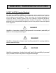
DANGERS, WARNINGS & CAUTIONS SAFETY ALERTS (Required Reading!) The following SAFETY ALERTS are intended to create awareness of owners, operators, and maintenance personnel of the potential safety hazards and the steps that must be taken to avoid accidents. These same alerts are inserted throughout this manual to identify specific hazards that may endanger uninformed personnel. Identification of every conceivable hazardous situation is impossible.
DANGERS, WARNINGS & CAUTIONS Read and understand this manual and all labels prior to operating or servicing the lift. All labels are provided in accordance with ANSI Z535.4. DANGER! Do not work under lift without maintenance device! To avoid personal injury, NEVER go under the lift platform until the load is removed and the scissors mechanism is securely blocked in the open position. See "Lift Blocking Instructions" section.
DANGERS, WARNINGS & CAUTIONS DANGER! Do not attempt to remove the velocity fuse until the maintenance locks securely support the lift and all hydraulic pressure has been removed from the lifting cylinders and hydraulic hoses. Failure to do so could result in personal injury or death! WARNING! Do not operate this equipment without handrails and snap chains in place. WARNING! Under no circumstances should the speed control orifice be removed from the Deltatrol to obtain faster lowering speed.
DANGERS, WARNINGS & CAUTIONS CAUTION! Never run the pump for more than a couple of seconds without pumping oil. This applies to low oil conditions, improper motor rotation, running the pump against the relief pressure after the lift is fully raised against the physical stops, running overloaded beyond capacity, or running at reduced speed because of pinched or obstructed hydraulic lines.
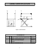
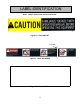
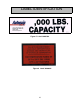
LABEL IDENTIFICATION Figure 1 Label Placement PLD Scissors Lift Item No. Qty Description 1 2 Caution: Familiarize Yourself With Operators Manual 2 2 Danger – Do Not Put Hands Or Feet . . . 3 1 Autoquip Serial Number Nameplate 36401511 4 2 Capacity 36401586 5 1 Fill with Recommended Oils Only 36400661 8 Part No.
LABEL IDENTIFICATION Note: Labels shown here are not actual size.
LABEL IDENTIFICATION Figure 5 Label 36401594 Figure 6 Label 36400661 10
SPECIFICATIONS Model Lifting Cap. (lbs) Std. Motor HP Axle Load Capacity Over Bridge End (lbs) Max Raised Height (Inches) Min.
LIFT BLOCKING INSTRUCTIONS 1. Remove all load from the platform. Never block the lift when loaded. 2. Raise the platform sufficiently for the base rollers to rollback past the flip-over maintenance locks, located on the base frame of the lift. 3. Engage both maintenance locks by flipping them into the base frame (see Figure 7). 4. Lower the platform until the base rollers come into contact with and rest against the maintenance locks.
LIFT BLOCKING INSTRUCTIONS FLIP-OVER MAINTENANCE LOCKS SHOWN IN PLACE ON BOTHSIDES OF BASE FRAME.
INSTALLATION INSTRUCTIONS CAUTION! Precautions should be taken to prevent the introduction of contaminates such as dirt or other foreign material into the system through open fittings, pipes or disassembled components. Contamination will ruin the hydraulic system. 1. Make temporary hose connections with high-pressure hose (see chart below) to allow the lift to be operated when it is set in the pit. Hydraulic Piping/Hose Size Up to 25 feet _” ID 26 feet to 50 feet _” ID Over 50 feet 1” ID 2.
INSTALLATION INSTRUCTIONS Leveling to Grade 1. The platform top should be solid and flush with the pit curb angles. The pit depth includes _” added to the lowered height of the lift for leveling purposes (see Figure 8). 2. Fully lower the lift platform into the pit and check for proper height. 3. Shims and/or grout must be placed under the entire base frame assembly and the platform support members to support the platform top at grade level.
INSTALLATION INSTRUCTIONS 6. Bumper posts are recommended to protect the lift from horizontal force when in the raised and lowered position. Clean Up 1. Clean up any spilled oil and debris from the area. A clean installation makes a good impression and creates a much safer environment! 2. Touch-up paint is available by request from Autoquip for repair of damaged paint surfaces.
INSTALLATION INSTRUCTIONS Figure 8 Bridge Installation, Steel 17
OPERATING INSTRUCTIONS Familiarize yourself with this operator’s manual before operating the equipment!!! 1. Scissors lifts have maximum lifting capacity ratings (see “Specifications” section). The safety relief valve has been factory set to open at a pressure slightly above the rated load capacity and allows the oil to bypass into the reservoir to prevent damage to the lift and its hydraulic power unit.
ROUTINE MAINTENANCE Normally scissors lifts will require very little maintenance. However, a routine maintenance program could prevent costly replacement of parts and/or downtime. WARNING! To avoid personal injury, NEVER go under the lift platform or perform any maintenance on the lift until the load is removed and the scissors mechanism is securely blocked in the open position. See "Lift Blocking Instructions" section. MONTHLY INSPECTION 1.
ROUTINE MAINTENANCE Oil Viscosity Recommendations Environment (Ambient Temperatures) Recommended Oil Indoor location, variable temperatures (30 - 100° F) 10W30 or 10W40 Multiviscosity motor oil Indoor location, consistent Temperatures (70° F) SAE-20W motor oil Outdoor location, (-10 - 100° F) SAE 5W30 Multiviscosity motor oil Cold-storage warehouse (10 - 40° F) 5W30 Multiviscosity motor oil Freezer (-40° F to 0° F) Consult Factory OIL CAPACITY Reservoir capacity for the self-contained tank is ap
GENERAL MAINTENANCE DANGER! HIGH VOLTAGE!! Disconnect and/or lock out the electrical supply to the power unit prior to any maintenance being performed. 1. Change oil once a year or when it materially darkens or feels gritty. Also, check oil for the presence of water (oil will turn milky in color.) 2. NEVER TRY TO DISASSEMBLE OR REPAIR A PUMP IN THE FIELD. These pumps are high-precision devices requiring extreme precision in fit-up.
GENERAL MAINTENANCE DANGER! HIGH VOLTAGE!! Disconnect and/or lock out the electrical supply to the power unit prior to any maintenance being performed. INTERNAL POWER UNITS Because Autoquip "Super-Torque" motors actually deliver substantially more horsepower than their nameplate rating, they must always be wired for heavier currentdraw than standard motors of the same nameplate rating.
GENERAL MAINTENANCE 2. The following should be referenced in connecting the standard heavy-duty motors to power sources. Remember that heavy wire must be used all the way to the power source. Power Unit 115 Volts 208 Volts 230 Volts 460 Volts Standard Three Phase N/A 16 amps 15.2 amps 7.6 amps Standard Single Phase 58 amps N/A 24.5 amps N/A NOTE: All amperage draws shown are full-load amperages. MOTOR CONNECTION DIAGRAMS AIR BLEEDING PROCEDURE 1.
GENERAL MAINTENANCE CYLINDER AND/OR SEAL REPLACEMENT Cylinder Removal 1. Lower the lift to the fully lowered position. 2. Continue to hold the “DOWN” button an additional 10 seconds after the lift has stopped traveling downward to relieve the system pressure. 3. Always shut off the main electrical switch when maintenance is to be performed. 4. Unbolt the two hex head bolts that connect the cylinder to the platform. 5. Disconnect the hydraulic hose from the cylinder.
GENERAL MAINTENANCE Re-Installing the Cylinder 1. Reinstall the new cylinder in the reverse procedure of the above instructions. 2. Once the cylinder is in place and all hydraulic connections are made tight, proceed to bleed air out of the system (see “Air Bleeding Procedure” section). 3. Check the oil level. 4. Clean up any debris and/or spilled oil from the area.
AIR BLEEDER SCREW W/ WASHER ROD END STOP 26 RAM CASING RAM CASING DETAIL A 1/4" - 90° FORGED STEEL ELBOW (3000 P.S.I.) GARFILL BUSHING Figure 9 Ram Detail GARFIL BUSHING (2 REQ'D) SPACER TUBE TRUNNION (2 REQ'D) SEAL/PACKING GLAND GLASS FILLED BACKUP RING QUAD RING RAM PLUNGER IN RETRACTED POSITION FOR SEAL REPLACEMENT. SEAL PACKING GLAND RAM PLUNGER (1 1/2" DIA.
GENERAL MAINTENANCE VELOCITY FUSE REPLACEMENT DANGER! Do not attempt to remove the velocity fuse until the lift is securely supported with the maintenance locking devices and all hydraulic pressure has been removed from the lifting cylinders and hydraulic hoses. Failure to follow these instructions could result in personal injury or death! Never attempt to take a velocity fuse apart and repair it. These are precision devices that are factory assembled under exacting conditions.
GENERAL MAINTENANCE ROCK SALT It has been discovered that rock salt is being used to melt the ice and snow off of the platforms in the northern region and during the winter months. Rock salt will accelerate the deterioration of any paint. Therefore, Autoquip recommends the use of a synthetic “Ice Melt” product in lieu of rock salt. Warranty on the paint finish will be denied when it is suspected that rock salt has been used.
GENERAL MAINTENANCE Figure 10 Hydraulic Schematic GENERAL29MAINTENANCE
Figure 11 Electrical Schematic; 230V/1PH (PLD-50) 30 DN UP * WHT. PUSHBUTTON 2 2 2 L2 L1 JUMPER (WHEN USED) *GRN. 6 *RED. 4 *BLK. (14) 6 L1 (X2) L2 AUX. CONTACT (51) 7 + - R DN. SOL. (BY AUTOQUIP) BLU. AUDIBLE SIGNAL (WHEN USED) 6 AS 3 FLASHING RED LIGHT (WHEN USED) ORG. (96) O.L. RELAY CONTACT (95) 3 3 3 3 FIELD WIRING TYP. (BY OTHERS) T3 3 T2 L3 T1 L2 L1 O.L. MOTOR STARTER CONTACTS TRANSFORMER MOTOR STARTER L2 L1 (A2) CC CONTACTOR COIL (A1) AUX.
GENERAL MAINTENANCE Figure 12 Electrical Schematic; 115V/1PH (PLD-20, 30) 31
GENERAL MAINTENANCE Figure 13 Pushbutton Assembly 32
REPLACEMENT PARTS LIST MODELS PLD 20 & 30 PART # DESCRIPTION 20022851 Clevis Pin Bushing 18DU12 20023965 Pivot Pin Bushing 24DU24 30000020 Motor, _ HP, 115-230/60/1/42 Fr/Tang/1725 RPM 32701290 Solenoid, 24VAC 32701370 Solenoid, 115 VAC 35104400 Control Panel Kit, Motor Starter & Fuse Holders 36202150 Push Button 40200255 Pump, 1.
REPLACEMENT PARTS LIST MODEL PLD 50 PART # 20000030 20000154 20000162 20022877 20024006 22170205 30000670 32701380 35150153 36202161 40300162 41050900 41800558 42300467 44810380 45400082 45400249 45901014 46000022 46000048 46100390 46000071 46000089 46000097 46000430 46000139 46200267 47300629 47700208 48101315 48200067 52502705 52502697 52502432 52600269 64000813 DESCRIPTION Pump Coupling Motor Coupling Coupling Spider Clevis Pin Bushing 18DU16 Axle Pin Bushing 24DU32 Cylinder Bleed Screw Motor, 5 HP Sole
TROUBLESHOOTING ANALYSIS DANGER! To avoid personal injury, NEVER go under the lift platform until the load is removed and the scissors mechanism is securely blocked in the open position. See "Lift Blocking Instructions" section. PROBLEM POSSIBLE CAUSE AND SOLUTION Lift does not raise. • The motor voltage/wiring may be incorrect. • The hydraulic line or hose may be leaking. • Oil in the reservoir may be low. Add oil as necessary (See the “Routine Maintenance” section.) • The load may exceed the rating.
TROUBLESHOOTING ANALYSIS PROBLEM Lift will not lower. POSSIBLE CAUSE AND SOLUTION The down solenoid may be malfunctioning. The maintenance leg could be installed. The structural members may be in a bind. The tubing or hose is obstructed or broken. Check for obstruction in the line. • The return filter may be clogged. • The velocity fuse may be locked. Do not attempt to remove the velocity fuse. The following steps should be followed: • • • • 1. Remove the load from the lift.
TROUBLESHOOTING ANALYSIS PROBLEM Lift raises slowly. POSSIBLE CAUSE AND SOLUTION • The structural members of the lift may be binding. • The tubing or hose is obstructed or broken. Where pipe is used, check for obstruction in the line. • The hydraulic line or hose may be leaking. • The oil viscosity is not suited for the environmental conditions. Refer to “Routine Maintenance” section for oil recommendations. • Check the oil level in the reservoir. • The motor voltage/wiring may be incorrect.
TROUBLESHOOTING ANALYSIS PROBLEM Lift will not remain in raised position. POSSIBLE CAUSE AND SOLUTION • The cylinder packing may be leaking. • The Deltatrol regulator is not seating. • The Deltatrol check valve is not seating. • The hydraulic tubing, hose, or fitting is leaking oil. • The return filter may be clogged.