
Instruction Manual

47
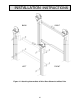
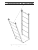
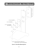
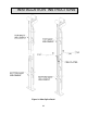
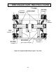
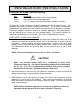
F. DRIVE BASE INSTALLATION DETAILS (Reference Figures 26 through 28)
Items needed:
Qty
Description
1 Drive Base w/Gearmotor, Shaft, Bearings & Sprockets
2 Front-to-Drive Base Channels (4”)
2 Back-to-Drive-Base Channels (4”)
varies 1/2" x 2”, Grade 8 Hex Head Cap Screw, Washer, and Nuts
4 1/2" x 5”, Grade 8 Hex Head Cap Screws
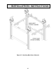
1. Raise the drive base into position above the mast beams in the orientation shown in
Figure 26 and bolt into place using the 1/2" x 5” long hex head cap screws provided.
Torque to 99 ft-lbs.
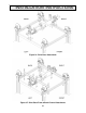
2. Bolt the (2) Front-to-Drive-Base channels and (2) Back-to-Drive-Base Channels into
place as shown in Figures 27 and 28 using the high grade 1/2" x 2” lg. bolts, lock
washers, and nuts provided. Torque to 99 ft. lbs.
INSTALLATION INSTRUCTIONS