INSTALLATION, OPERATION AND SERVICE MANUAL FREIGHTLIFT Model FL4M P.O. Box 1058 1058 West Industrial Avenue Guthrie, OK 73044-1058 888-811-9876 405-282-5200 FAX: 405-282-3302 www.autoquip.com 830FL4M Version 3.3 Dec.
TABLE OF CONTENTS Introduction & Company Contact Information 3 Inspection & Identification of Parts 4 Responsibility of Owners/Users 5 Safety Signal Words 6 Safety Practices 7 Safety Features 12 Label Identification 15 Specifications 18 Blocking Instructions 19 Installer Guidelines & Responsibilities 22 Installation Instructions 27 Operating Instructions 82 Routine Maintenance 87 General Maintenance 90 Replacement Parts List 92 Troubleshooting Analysis 93 Glossary of Terms 9
INTRODUCTION CODE REQUIREMENTS VRCs are NOT elevators. This lift is designed for the transfer of material only from one level to another. Absolutely NO RIDERS! VRCs have their own national safety code (ANSI/ASME B20.1) and are specifically exempt from the National Elevator Code. Some states require special components and have specific guidelines regarding how the equipment must be installed, inspected, and tested.
INSPECTION & IDENTIFICATION Your FREIGHTLIFT arrives packaged as follows: The four (4) masts and platform (either 1-piece or 2-piece if spliced) come on shipping skid(s), you also receive parts crate(s) which normally contain the following items: A. 48” H Side Guards/Handrails (Qty depends on platform size & layout) B. Six or more - 6” Intermediate Channels C. Two Front & Two Back - 6” Channels, Drive Base to Cross Channel D. (1) Back & (1) Front – 6” Mast Cross Channels; (2) 6” Drive Base Channels E.
RESPONSIBILTY OF OWNERS/USERS CODE COMPLIANCE Ultimate responsibility for gaining state and local code approval is the responsibility of the buyer of the VRC. Please acquaint yourself with the permitting and/or licensing expenses and requirements of the local regulatory agencies in the installation area. . INSPECTION & MAINTENANCE The lift shall be inspected & maintained in proper working order in accordance with this manual and with other applicable safe operating practices.
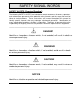
SAFETY SIGNAL WORDS SAFETY ALERTS (Required Reading!) The following SAFETY ALERTS are intended to create awareness of owners, operators, and maintenance personnel of the potential safety hazards and the steps that must be taken to avoid accidents. These same alerts are inserted throughout this manual to identify specific hazards that may endanger uninformed personnel. Identification of every conceivable hazardous situation is impossible.
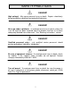
SAFETY PRACTICES DANGER! High voltage! May cause personal injury or death. Repairs should only be performed by a qualified service/control technician. DANGER! Never go under a platform! To avoid personal injury or death, always be sure the load has been removed from the platform and that it has been adequately blocked from underneath. See “Blocking Instructions” section. DANGER! Qualified personnel only!! Only qualified service personnel should perform procedures labeled as “dangerous”.
SAFETY PRACTICES DANGER! Practice field safety procedures! To avoid personal injury or death, utilize all applicable precautions for steel erection and equipment assembly in addition to OSHA Lock-Out, Tag-Out procedures. DANGER! Support all beams and components! Illustrations in this manual may show them unsupported. This is done in order to make the equipment and its installation clearly understood. Be sure to properly secure all lift beams and components on the actual unit.
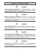
SAFETY PRACTICES WARNING! Slack chains require factory help! Do not attempt to repair slack chain conditions alone! Always contact the local representative or call the Autoquip Service Department at 888-811-9876. WARNING! Never run the unit with the gates or doors open! Do not operate unit with doors open or with the interlocks “defeated” (bypassed)! Serious injury or death could result.
SAFETY PRACTICES WARNING! Never operate unit when parts are broken or damaged! Do not operate this equipment when non-factory approved or damaged parts are in use! Contact the local FREIGHTLIFT Service Representative to rectify all such situations. WARNING! Use proper chain or chain master links! Never use chain or chain master links which are not properly rated for the intended use.
SAFETY PRACTICES CAUTION! Chains must be seated before raising lift! Be sure the chains are seated in the sprockets on top of the mast prior to raising the lift. CAUTION! Do not run carriage until limits are set! If the electrical is not complete, do not run the carriage all the way to the top or all the way back down until the limits are set. NOTICE Do not run the gear reducer when it is dry! Running the system in a dry condition can result in serious damage to the equipment.
SAFETY FEATURES There are several primary active safety features and devices to help protect personnel, property, and the equipment. LOCKING CAMS (Reference Figure 19) Each chain is terminated at the platform carriage in a clevis, which is attached to a tension spring loaded steel safety cam. This safety cam pivots on a high strength steel pin which is chrome plated. The safety cam has serrated teeth cut into one of its faces that are adjacent to the guide beam flange.
SAFETY FEATURES ELECTRICAL CURRENT SENSOR (ECS) (Reference Figure 40) The ECS with trip relay is used to prevent overloading of the FREIGHTLIFT by sensing an increase in the motor amps drawn should the carriage be overloaded or jammed. The increase of motor amps will kick the relay out and shut off the motor circuit. This condition will continue until the carriage overload or jam condition is removed/resolved. CONTROL TRANSFORMER SECONDARY FUSE This fuse is located in the control enclosure.
SAFETY FEATURES PERSONNEL GUARDS Depending on the application, one or more of the following personnel protection features is included in the design of this equipment (different states may vary on the exact design and orientation of these features – IT IS IMPORTANT TO BECOME FAMILIAR WHICH THE SPECIFIC CODE REQUIREMENTS OF YOUR STATE): - - GATES & ENCLOSURES: Required per ASME B20.1 to protect personnel from inadvertent physical contact with a moving lift & moving load at all lift landings.
LABEL IDENTIFICATION Field-locate & apply one “WARNING – Do Not Tamper” label adjacent to (within 6”-12”) each sensing device (limit switches, door status switches, door interlocks, etc.) in a location that is visible to the operator. BOTH SIDES 6 BOTH SIDES 6 ALL (4) CORNERS 1 3 4 BOTH SIDES 2 BOTH SIDES 5 BOTH SIDES Figure 1 FL4M Label Placement FL4M Description Item # Qty.
LABEL IDENTIFICATION Note: Labels shown here are not actual size.
LABEL IDENTIFICATION Figure 5 Label 36401586 Figure 7 Label 36403720 Figure 8 Label 36405705 Figure 9 Label 36405110 17
GENERAL SPECIFICATIONS Standard FL4M Models Model Max Travel Capacity (pounds) Platform (Min) WxL Platform (Max) WxL HP** (Min) Standard Speed (fpm) FL4M-6 100’ 6,000 6’ X 6’ 12’ x 15’ 7.5 25 FL4M-8 100’ 8,000 6’ X 6’ 12 x 15’ 7.
BLOCKING INSTRUCTIONS WARNING ! Only authorized personnel should perform inspection or maintenance and service procedures. Unauthorized personnel attempting these procedures do so at the risk of personal injury or death. DANGER ! Failure to properly adhere to lift these Blocking Instructions is to risk the sudden and uncontrolled descent of the lift carriage during maintenance or inspection. A falling carriage can cause severe injury or death. I. ROUTINE MAINTENANCE (Carriage is completely lowered) 1.
BLOCKING INSTRUCTIONS DANGER ! If for any reason you are unable to lower the lift completely onto the drums, stop immediately and consult the factory at 888-811-9876. Failure to use a system of adequately stable and strong lift blocking devices could result in severe injury or death. II.
BLOCKING INSTRUCTIONS III. BLOCKING FOR GEAR MOTOR/DRIVE MAINTENANCE DANGER! Do not remove or disconnect the motor, brake or drive chains unless the platform has been adequately blocked to prevent any downward movement, a falling platform will cause serious injury or death. Extreme caution must be taken anytime the gearbox, brake motor, or drive chains are disassembled.
INSTALLER GUIDELINES/RESPONSIBILITIES Proper installation of Vertical Reciprocating Conveyors (VRCs) is vital to the safety of the operators, the efficiency of the unit, and the ultimate satisfaction of the end user. These guidelines have been prepared by member companies of the Material Handling Industry’s VRC Subcommittee to assist the VRC installers in understanding their role and responsibility in providing customers with a safe and reliable VRC. 1. PRE-INSTALLATION ACTIVITY A.
INSTALLER GUIDELINES/RESPONSIBILITIES B. Assuming no damage has occurred to the crate, check the components against the packing list. This will help ensure that every item shipped has been received. C. Make sure you have a copy of the latest version of the general arrangement and electrical drawings before beginning installation, changes could have been made since original purchase order submittal and order entry. D. Read and understand this manual thoroughly prior to starting the installation. 3.
INSTALLER GUIDELINES/RESPONSIBILITIES 5. MECHANICAL INSTALLATION A. Most work can be done with the lift carriage fully lowered. Never work under the lift carriage unless it is blocked in place per the “Blocking Instructions” section of this manual. B. Never allow a person to ride on the carriage of the lift. C. Use only the hardware supplied by the Manufacturer to assemble the lift. This hardware is often high grade, some hardware is metric. D.
INSTALLER GUIDELINES/RESPONSIBILITIES I. Operator pushbutton stations must not be operable from the carriage with the gate(s) or door(s) closed, typically located at least 6 feet away from the carriage platform. J. Per OSHA requirements, the motor control panel must be mounted in a location that is visible from the lift. K. Always follow OSHA lock-out, tag-out procedures when the lift being maintained, serviced, or inspected. 7. PERSONNEL & EQUIPMENT SAFETIES A. ASME B20.
INSTALLER GUIDELINES/RESPONSIBILITIES 9. CLEAN-UP & HAND-OFF A. Conduct a final inspection of the lift installation using the Installation Checklist in the Appendix of this manual. Correct any deficiencies before clean-up & hand-off. B. Apply proper signage to all locations of the installation per the guidelines in the Label Identification section and per any instructions shipped separately with the gate interlock kits. Contact Autoquip at 888-811-9876 if labels appear to be missing or damaged. C.
INSTALLATION INSTRUCTIONS THE TOOLS REQUIRED FOR INSTALLATION Listed below are some of the tools needed to install the FREIGHTLIFT in a professional and prompt manner. Individual site situations and a basic variation in the types of units may dictate the need for additional items. Welding Machine and Equipment Cutting Torch with Full Tanks Fire Extinguisher Forklift Chain Fall Come-A-Long Cables or Hook Chains with 1,000# Cap.
INSTALLATION INSTRUCTIONS 6" X 13# BACK TO TO DRIVE BASE CHANNEL 6" X 12# BACK MAST CROSS CHANNEL GEAR MOTOR 6" X 13# FRONT TO DRIVE BASE CHANNEL DRIVE SHAFT 4" X 10" TUBE DRIVE BASE ASSEMBLY 6" X 16.
INSTALLATION INSTRUCTIONS NOTE: All illustrations contained in this manual are for reference purposes only. Specific applications and site conditions may require different anchoring and bracing procedures. The ultimate responsibility for the anchoring and bracing rests with the installation crew. A. LAYING OUT CARRIAGE POSITION & MARKING FLOORS FOR ALLIGNMENT 1.
INSTALLATION INSTRUCTIONS Figure 11 Marking the 2nd Floor for Carriage Position (Front View) Figure 12 Locating Center of Carriage Edge on the First Floor (Side View) 30
INSTALLATION INSTRUCTIONS Figure 13 Locating Center of Carriage Edge on the First Floor (Front View) Figure 14 Locating Outside Edges of Carriage at the First Floor (Front View) 31
INSTALLATION INSTRUCTIONS C B D Figure 15 Chalking the Edge of the Carriage at the First Floor (Front View) Figure 16 Aligning Carriage with Chalk Line 32
INSTALLATION INSTRUCTIONS HANDRAIL CARRIAGE WELDMENT CARRIAGE UPRIGHT Figure 17 Carriage Assembly 33
INSTALLATION INSTRUCTIONS Installation is basically simple, requiring only normal tools. However, the beams must be lifted into position. These are too heavy to lift manually and require lifting equipment. Check for availability of overhead attachment of chain fall or of fork truck before start. B.
INSTALLATION INSTRUCTIONS 10" (TYPICAL) CENTER OF MAST BEAM WEB CARRIAGE LENGTH + 2" (MIN.
INSTALLATION INSTRUCTIONS C. POSITIONING WHEEL GUIDE ASSEMBLIES (Reference Figures 19 and 20) Items Needed: Description Qty 4 Mast Beams – Left Front, Right Front, Left Back, Right Back 2 Left Hand Wheel Guides – Marked with “L” on the assembly 2 Right Hand Wheel Guides – Marked with “R” on the assembly 4 Chain Adpators 8 Cotter Pins 4 Chain Adaptor Pins (with cotter pin holes) 4 Master Links (chain size varies) 1.
INSTALLATION INSTRUCTIONS GUIDE ANGLE WHEEL GUIDE ASSEMBLY LOCKING CAM MAST BEAM Figure 19a Upper Wheel Guide Assembly in Mast Beam (Top View) Figure 19b Upper Wheel Guide Assembly in Mast Beam (Side View) 37
INSTALLATION INSTRUCTIONS Figure 20 Upper Wheel Guides – Field Welding of Reinforcement Bars 38
INSTALLATION INSTRUCTIONS D. RAISING THE BEAMS & WHEEL GUIDES (Reference Figures 21 through 24) Items Needed: Qty Description 2 Drive Base Channels (6” channel) Varies Intermediate Channels (6” channel) 2 Installation Angles (with holes drilled in each end) varies 1/2" x 2” grade 8 Hex Head Cap Screws, Washers & Nuts 1. The masts are designated “left front” , “right front”, “left back”, and “right back” with a welded “LF” , “RF”, “LB” and “RB” marked on the mast beam base plate.
INSTALLATION INSTRUCTIONS SPLICED BEAMS (when used) 1. Set the upper mast on its respective lower mast (plates & beams are marked) in the orientation shown on Figure 24, taking necessary precautions not to bend or damage transition plates. 2. Verify that all four beams are true, straight, and plumb within 1/8” over any 10 foot span and not to exceed 3/8” over the entire length of the beam. NOTE: This tolerance may not be exceeded or immediate & permanent damage to the hardened wheel guide wheels will occur.
INSTALLATION INSTRUCTIONS Figure 21 Attaching Intermediate & Drive Base Channels to Mast Pairs 41
INSTALLATION INSTRUCTIONS Figure 22 Raising the Mast Beam Assemblies 42
INSTALLATION INSTRUCTIONS Figure 23 Wheel Block Mounting Detail 43
INSTALLATION INSTRUCTIONS Figure 24 Mast Splice Detail 44
INSTALLATION INSTRUCTIONS E. JOINING & SECURING THE MASTS (Reference Figure 25) Items needed: Qty Description 2 Mast Cross Channels (6”) varies 1/2" x 2”, Grade 8 Hex Head Cap Screws, Washers, and Nuts 1. Join the Left mast pair assembly to the Right mast pair assembly by installing the front and back mast cross channels using the 1/2" x 2” lg. bolts, lock washers, and nuts provided. These channels are stamped LB, RB (left back, right back) and LF, RF (left front, right front) for proper orientation.
INSTALLATION INSTRUCTIONS Figure 25 Attaching Mast Cross Channels 46
INSTALLATION INSTRUCTIONS F. DRIVE BASE INSTALLATION DETAILS (Reference Figures 26 through 28) Items needed: Description Qty 1 Drive Base w/Gearmotor, Shaft, Bearings & Sprockets 2 Front-to-Drive Base Channels (4”) 2 Back-to-Drive-Base Channels (4”) varies 1/2" x 2”, Grade 8 Hex Head Cap Screw, Washer, and Nuts 4 1/2" x 5”, Grade 8 Hex Head Cap Screws 1.
INSTALLATION INSTRUCTIONS Figure 26 Drive Base Attachment Figure 27 Drive Base Front & Back Channel Attachment 48
INSTALLATION INSTRUCTIONS MAST CROSS CHANNEL LEFT BACK MAST HEAD ASSEMBLY 1 BACK TO DRIVE BASE CHANNEL LEFT BACK MAST HEAD ASSEMBLY 1 DRIVE BASE CHANNEL DRIVE BASE CHANNEL 1 LEFT FRONT MAST HEAD ASSEMBLY BACK TO DRIVE BASE CHANNEL RIGHT FRONT MAST HEAD ASSEMBLY MAST CROSS CHANNEL Figure 28 Completed Drive Base Layout – Top View 49 1
INSTALLATION INSTRUCTIONS G. BRACING THE BEAMS (Reference Figure 29) Items Need: Description Qty Varies Horizontal Channel Brace (with 4-hole lag plate) Varies Side Channel Brace (when applicable) Varies 1/2" x 2”, Grade 8 Hex Head Cap Screw, Washers, and Nuts All illustrations on the GA drawing for bracing preferences are for reference only. Site conditions may require different anchoring and bracing. The installers are ultimately responsible for the proper and safe anchoring and bracing of the equipment.
INSTALLATION INSTRUCTIONS WARNING! Do not weld on the guide flanges of the masts. The field welding of any structural steel member into or across the guide beams in the path of the wheel guides is strictly forbidden.
INSTALLATION INSTRUCTIONS ANCHORING TO BLOCK WALLS USE BACKUP PLATES WRONG WELD TO CURB ANGLE ANCHORING TO FACE OF FLOOR RIGHT WRONG WOODEN FLOORS PREFERRED THROUGH BOLTING POOR Figure 29 Approved Methods for Upper Level Mast Bracing 52
INSTALLATION INSTRUCTIONS THROUGH - FLOOR CORNER LOCATION Figure 29 (cont’d) Approved Methods for Upper Level Mast Bracing 53
INSTALLATION INSTRUCTIONS MEZZANINE APPLICATION Figure 29 (cont’d) Approved Methods for Upper Level Mast Bracing 54
INSTALLATION INSTRUCTIONS H. INSTALL DRIVE CHAINS & LIFTING CHAINS (Reference Figures 30 to 33) Items needed: Qty Description 4 Lifting Chains 4 Drive Chains (the drive chains will be shorter than the lifting chains) 4 Counterweights 4 Lifting Chain Master Link Assemblies 4 Drive Chain Master Link Assemblies 1. Familiarize yourself with the drive base layout on top of the lift, ensure that all components are present and oriented as shown in Figure 28. 2. Install drive chains between the 17-tooth (approx.
INSTALLATION INSTRUCTIONS Figure 30 Drive Chain Path 56
INSTALLATION INSTRUCTIONS SLACK CHAIN Figure 31 Lifting Chain Path 57
Figure 32a Locking Cam Attachment 58 NOTES: LEFT HAND LOCKING CAM SHOWN. (2) RIGHT HAND LOCKING CAMS AND (2) LEFT HAND LOCKING CAMS REQUIRED.
INSTALLATION INSTRUCTIONS LIFTING CHAIN BEND ENDS OF COTTER PIN ONCE INSERTED INTO HOLE UPPER GUIDE WHEEL ASSEMBLY Figure 32b Locking Cam Attachment 59
INSTALLATION INSTRUCTIONS LIFTING CHAIN LIFTING CHAIN MASTER LINK BASE MATER LINK RETAINING CLIP COUNTERWEIGHT MASTER LINK COVER PLATE COUNTERWEIGHT Figure 33 Counterweight Connection 60
INSTALLATION INSTRUCTIONS I. WIRING THE EURODRIVE BRAKE MOTOR EURODRIVE gear motors are designed and manufactured with totally enclosed, fancooled, squirrel-cage induction motors which are designed for operation under difficult conditions. The windings are protected with a special insulating material Class B equivalent or better.
INSTALLATION INSTRUCTIONS J. LEVELING THE CARRIAGE (Reference Figure 34) WARNING! When running the unit before ALL limit switches are installed, be prepared to disconnect power on demand. Allowing carriage overtravel in either direction can result in severe damage to the equipment and potential injury to standers-by. Temporary power must NOT be used. 1. Make sure the carriage is free to rise about six (6) inches. Check to be sure carriage is level and chains are equally tight. 2.
INSTALLATION INSTRUCTIONS Figure 34 Lifting Chain Tension Adjustment 63
INSTALLATION INSTRUCTIONS K. INSTALLING LEVEL/OVER-TRAVEL LIMIT SWITCHES (Ref. Figures 35 and 36) Items needed: Description Qty Varies Level Limit Switch Kits 1 Over-Travel Limit Switch Kit 1 Maintained Contact Limit Switch Kit (mid-level on 3-level applications only) DANGER! Never go under a platform! To avoid personal injury or death, be sure the platform has been blocked from underneath! See “Blocking Instructions.” LEVEL LIMIT SWITCHES (Fig.
INSTALLATION INSTRUCTIONS Field-locate & apply one “WARNING – Do Not Tamper” label adjacent to (within 6”-12”) each sensing device (limit switches, door status switches, door interlocks, etc.) in a location that is visible to the operator.
INSTALLATION INSTRUCTIONS UniStrut Nut & Spring UniStrut Channel Switch Arm Switch Actuator Switch Head Mounting Angle Hardware Switch Body 10-24 Socket Head Cap Screws Figure 36 Level Limit Switch Kit Assembly 66 Mounting Angle
INSTALLATION INSTRUCTIONS Loosen 8-32 socket head cap screw to adjust arm in and out, then re-tighten Loosen 8-32 socket head cap screw to adjust arm rotation, then re-tighten Loosen (4) flat head machine screws to rotate head, then re-tighten Switch actuator Figure 37 Sensing Switch Adjustments 67
INSTALLATION INSTRUCTIONS L. INSTALLING SLACK CHAIN SENSING SWITCHES (Reference Figures 38a&b) Items needed: Qty Description 4 Slack Chain Sensing Switch Kit – Lifting Chains Kits have been shipped loose to be field mounted, wired, and adjusted per the procedure below for the lifting chains. Sensing switches have been pre-mounted (but not been adjusted) onto the drive base for the drive chains.
INSTALLATION INSTRUCTIONS Sprocket Chain tensioner wheel Tensioner arm Tensioner bar Socket head cap screws & lock washers Mounting Plate (pre-mounted) Switch body Switch actuator Figure 38a Slack Chain Sensing Switches – Lifting Chains (mounting switch) 69
INSTALLATION INSTRUCTIONS Switch arm rests against tensioner bar Tensioner bar Figure 38b Slack Chain Sensing Switches – Lifting Chains (completed) 70
INSTALLATION INSTRUCTIONS f. While still holding the actuator in place with the needle nose pliers, tighten the switch arm onto the actuator with the socket head cap screw provided g. You can now release the needle nose pliers from around the actuator NOTE: To change the actuation direction of the switch, remove the switch head. Change the switch actuator to the desired actuation direction, then re-tighten the (4) machine screws holding the switch head to the switch body. (Reference Figure 37) 3.
INSTALLATION INSTRUCTIONS 7. Once confirmed that all slack chain sensing switches shut the motor off as required, chain tension must be re-established in all lifting chains. Because the slack chain sensing switches are now set properly, the motor will not run to lift the chains.
INSTALLATION INSTRUCTIONS 13. After installing these drive chain sensing switches, they should be tested to make sure they are adjusted and set correctly. A qualified electrician should, while referencing the lift’s electrical schematic, test the electrical continuity of each drive chain sensing switch inside the lift’s motor control panel to make sure that the contacts in the switch are in the closed condition when in the running position with an unloaded carriage.
INSTALLATION INSTRUCTIONS Double sprocket Step 11 Tensioner arm Tensioner roller Sensing Switch adjustments slide into loaded tensioner arm until electrical contacts made Step 10 Tensioner adjustments – slide into taut chain until spring-loaded tensioner arm has rotated Switch arm must align with and push against tensioner arm Step 9 Tensioner/Sensing Switch assembly adjustment left or right as required to align tensioner roller with taut chain Figure 38c Slack Chain Sensing Switches – Drive Chains (
INSTALLATION INSTRUCTIONS M. INSTALLING COUNTERWEIGHT SENSING SWITCH (Reference Figure 39) Items needed: Description Qty 1 Counterweight Sensing Switch Kit This kit has been shipped loose to be field mounted, wired, and adjusted per the procedure below. These switches are intended to turn off the motor whenever a counterweight attempts to come out the top of its guide tube during lift operation. 1. To install the counterweight sensing switch, first gain safe access to the top of the masts.
INSTALLATION INSTRUCTIONS SWITCH ARM COUNTERWEIGHT TUBE MOUNTING PLATE Figure 39 Counterweight Limit Switch Locations (2 req’d) 76
INSTALLATION INSTRUCTIONS N. TEST RUN (EMPTY) & MAKE ADJUSTMENTS DANGER! Never go under a platform! To avoid personal injury or death, be sure the platform has been blocked from underneath! See “Blocking Instructions.” WARNING! Never operate the lift by “manualling” the electrical controls (using the contactors located inside the control panel). All safety devices are bypassed in this mode of operation and lift damage or severe personal injury could occur.
INSTALLATION INSTRUCTIONS 4. Raise the Freightlift 3-6 feet (again, you must stop the lift using the E-Stop button) above the floor. Is everything okay? Any unusual noises? Are masts stable or do they need additional bracing? 5. If you are satisfied with the alignment and structural integrity of the unit, cycle the platform carriage higher & higher until the top landing is eventually reached, continuing to check the smoothness of operation.
INSTALLATION INSTRUCTIONS P. BACK-STOP KIT (when ordered) Separate back-stop installation drawings are provided with the back-stop kit. Installer must ensure that the finished distance between the edge of carriage and the inside of the back-stop panels does not exceed 4 inches. Q. ELECTRICAL CURRENT SENSOR (ECS) with TRIP RELAY (Reference Fig. 40) The ECS works with a timed, trip delay relay, which bypasses the sensor during every motor start up.
INSTALLATION INSTRUCTIONS 3. Once the lift will operate with the nameplate capacity on the lift carriage, add an additional 15% to the amp draw reading on the dial. Run the lift several times to make sure your setting is correct and the carriage will run full up and down without tripping ECS off. If the ECS does still trip off go back to step one and repeat setting requirements.
INSTALLATION INSTRUCTIONS R. INSTALLATION WRAP-UP 1. After the unit is completely wired, make all necessary and final adjustments to ensure proper operation of the lift and its safeties as required by the schematic. 2. Refer to the Inspection Checklist located in the Appendix of this Manual, and confirm the safe and correct condition of each component/feature listed to ensure that the lift is ready to be given to the User in proper & safe working condition.
OPERATING INSTRUCTIONS DANGER! To avoid personal injury or death, do not operate this equipment with nonfactory, damaged, or missing parts or equipment supports. Contact a local FREIGHTLIFT service representative if a deficiency is found. WARNING! No riders! The FREIGHTLIFT is provided for the sole purpose of transporting goods between floor elevations. At no time should it be used to transport personnel.
OPERATING INSTRUCTIONS 2. The motor turns the gears in the reducer, which in turn rotates the drive shaft. The sprockets on the shaft also turn resulting in the raising or lowering of the lifting chains (because the motor starter is reversible, the direction of travel can be alternated). The lifting chains are fastened to the wheel blocks, which are in turn bolted to the carriage, thereby raising or lowering the carriage. 3.
OPERATING INSTRUCTIONS DOWN 1. When a DOWN button on a push button station is pressed & released, the control (secondary) circuit to the motor starter (motor contactor) is completed. The coil of the motor starter magnetically closes the high (primary) voltage contacts completing the power circuit to the motor causing the reversing motor starter to engage and start the motor. 2.
OPERATING INSTRUCTIONS PREVENTING DAMAGE TO THE LIFT 1. Exceeding the Capacity of the Lift The load capacity rating is stamped on a metal serial number plate attached to the lift. This figure is a net capacity rating for a lift furnished with the standard platform. The Electrical Current Sensor (ECS) has been set to raise the weight, plus a small amount for overload.
OPERATING INSTRUCTIONS B. DO NOT walk out onto the carriage or attempt to physically free the jam until the carriage has been safely supported from beneath per instructions given in the “Lift Blocking” section of this manual. C. DO Call Autoquip (888-811-9876) to provide assistance in discovering the source & acceptable remedy for the carriage jam. D.
ROUTINE MAINTENANCE DANGER! To avoid personal injury or death, all maintenance procedures described in this section should only be performed by qualified service personnel. DANGER! To avoid personal injury or death, do not operate this equipment with substandard, defective, or missing parts. Contact a local FREIGHTLIFT service representative if a deficiency is found.
ROUTINE MAINTENANCE DANGER! To avoid personal injury or death, before performing any static inspections, make sure the platform carriage is fully lowered and the power has been disconnected at the safety disconnect switch. Also, put signs at all gates, doors, controls, etc. indicating that the system is out of service for maintenance per OSHA Lock-Out, Tag-Out procedures. Inspection List – Every 3 Months (1,000-1,200 hours of operation): 1.
ROUTINE MAINTENANCE Inspection List – Every 12 Months (4,000-5,000 hours of operation): 1. Conduct a full inspection of the unit by using the comprehensive Inspection Checklist found in the Appendix of this manual. 2. Check the gear oil level in the gear reducer. Gear oil should be flush with the bottom threads of the appropriate check plug. The fill and breather holes will be the top hole on one side and the fluid check hole will be a plug about half way up on the gear reducer.
GENERAL MAINTENANCE DANGER! To avoid personal injury or death, the procedures described in this section should only be performed by qualified service personnel. WARNING! Never operate the lift by “manualling” the electrical controls (using the contactors located inside the control panel). All safety devices are bypassed in this mode of operation and lift damage or severe personal injury could occur.
GENERAL MAINTENANCE ADJUSTING COUNTERWEIGHT SENSING SWITCHES To ensure proper setting and performance of the Counterweight Sensing Switch, follow the procedure set forth in Paragraph M of the “Installation” section. NOTE: Should you have any questions or need assistance please call Autoquip Customer Service (888-811-9876). ADJUSTING THE ECS CURRENT SETTING DANGER! Secure platform and chains! Do not remove or disconnect the motor or brake unless the platform and chains have been secured.
REPLACEMENT PARTS LIST Specific part numbers vary from job to job, depending on the model and options chosen for the application. Call the Autoquip Service Department at (405) 282-5200 or 1-888811-9876 with the serial number of the specific FREIGHTLIFT equipment to order the appropriate parts.
TROUBLESHOOTING ANALYSIS DANGER! To avoid personal injury, NEVER go under the lift platform until it is securely blocked (See "Blocking Instructions" section) and the load is removed.
TROUBLESHOOTING ANALYSIS PROBLEM Freightlift will not raise (motor is running or “humming”). WARNING! a safety device may have been activated – if you are not familiar with how safety devices interact with the operation of the lift, you must find someone who does. Or, call Autoquip Customer Service at 888-811-9876. POSSIBLE CAUSE AND SOLUTION WARNING! The lifting chains may be disconnected or broken and slack chain sensing switches missing or malfunctioning.
TROUBLESHOOTING ANALYSIS PROBLEM Freightlift will not lower (electrically). WARNING! The lifting chains may be disconnected and slack chain sensing switches missing or malfunctioning. Check while standing near (but NOT on) the lift carriage and correct as necessary – once carriage has been blocked in place. WARNING! a safety device may have been activated – if you are not familiar with how safety devices interact with the operation of the lift, you must find someone who does.
GLOSSARY OF TERMS TERM DEFINITION Anchors Bolts used to fix masts to the floor ATF Automatic transmission fluid Back frame The vertical portion of the carriage on the cantilever Freightlift Cantilever A style of Freightlift where the carriage rides along two masts that are mounted on the same side of the carriage. This style of lift will accommodate all three loading patterns.
GLOSSARY OF TERMS TERM DEFINITION Motor starter A motor controller component for accelerating a motor from rest to normal speed. Non-operating end The side(s) of the platform not used for loading/unloading. Handrails with midrails and kick plates are supplied as minimum safety protection. Operating end The side(s) of the platform used for loading/unloading. A safety chain is supplied as minimum safety protection.
APPENDIX INSPECTION CHECKLIST This checklist is intended to assist qualified maintenance and inspection personnel to inspect Freightlift installations for proper installation and maintenance concerns. The lift should be run several times, and carriage sent to each loading level, in unloaded condition for static inspection, and loaded condition during the dynamic inspection. In this way, a wider variety of issues will present themselves as actual operating conditions are duplicated as closely as possible.
APPENDIX C. MECHANICAL Y 1 Lifting chain system is installed properly (pp: 24, 55-63, 88) a. lifting chain has correctly sized & installed master links? (keepers in place, also look for excessive number of master links) b. chain adaptor/pins/keepers are factory-supplied & undamaged? (look for egging, rounding or extrusion of metal at edge of pin holes) c. lifting chain is aligned with, and properly engaging, sprockets? (look for cracked/missing teeth, excessive wear, binding on sprocket) d.
APPENDIX 1 2 3 4 5 6 7 8 9 10 11 12 13 14 E. PERSONNEL & EQUIPMENT SAFETIES Have all operators been formally trained to use this lift? (pg.5) (and do they have a copy of the manual) Are gates & enclosures installed around lift per ASME B20.1?(p.78) (are they secure, stable, able to keep out personnel?) (pp.14,25) Do all Gate interlocks function properly? (pp.13, 82) (gate must NOT open if carriage is NOT at that level) Are all Safety Labels on the carriage? (pp.
LIMITED WARRANTY The user is solely responsible for using this equipment in a safe manner and observing all of the safety guidelines provided in the Owner’s Manual and on the warning labels provided with the lift. If you are unable to locate either the manual or the warning labels, please contact Autoquip (888-811-9876) or access www.autoquip.com for replacement downloads or information.