INSTALLATION, OPERATION AND SERVICE MANUAL COMPACT LIFT P.O. Box 1058 1058 West Industrial Avenue Guthrie, OK 73044-1058 888-811-9876 405-282-5200 FAX: 405-282-3302 www.autoquip.com Item #830AMP Version 2.
TABLE OF CONTENTS Identification and Inspection 3 Responsibility of Owners / Users 4 Safety Signal Words 5 Safety Practices 6 Label Identification 10 Specifications 13 Lift Blocking Instructions 15 Installation Instructions 18 Operating Instructions 23 Routine Maintenance 24 General Maintenance 26 Replacement Parts List 34 Troubleshooting Analysis 37 Warranty 41 IMPORTANT Please read and understand this manual prior to installation or operation of this lift.
IDENTIFICATION & INSPECTION IDENTIFICATION When ordering parts or requesting information or service on this lift, PLEASE REFER TO THE MODEL AND SERIAL NUMBER. This information is on a nameplate attached to the leg assembly. Replacement parts are available from a local Autoquip distributor. INSPECTION Immediately upon receipt of the lift, a visual inspection should be made to determine that it has not been damaged in transit. Any damage found must be noted on the delivery receipt.
RESPONSIBILTY OF OWNERS/USERS DEFLECTION It is the responsibility of the user/purchaser to advise the manufacturer where deflection may be critical to the application. INSPECTION & MAINTENANCE The lift shall be inspected and maintained in proper working order in accordance with Autoquip’s operating/maintenance (O&M) manual and with other applicable safe operating practices.
SAFETY SIGNAL WORDS SAFETY ALERTS (Required Reading!) The following SAFETY ALERTS are intended to create awareness of owners, operators, and maintenance personnel of the potential safety hazards and the steps that must be taken to avoid accidents. These same alerts are inserted throughout this manual to identify specific hazards that may endanger uninformed personnel. Identification of every conceivable hazardous situation is impossible.
SAFETY PRACTICES Read and understand this manual and all labels prior to operating or servicing the scissors lift. All labels are provided in accordance with ANSI Z535.4. DANGER! Do not work under lift without Maintenance Device! To avoid personal injury, NEVER go under the lift platform until the load is removed and the scissors mechanism is securely blocked in the open position. See "Lift Blocking Instructions" section.
SAFETY PRACTICES DANGER! Scissors lifts are designed individually for a specific load and application. To avoid personal injury, do not change the load or application from the original design. WARNING! NEVER stand, sit or ride on the lift! WARNING! All warning and information decals should be in place as outlined in the “Label Identification” section. If decals are missing or damaged, they should be replaced with new ones. Contact Autoquip for replacements.
SAFETY PRACTICES WARNING! The hydraulic velocity fuse (HVF) must be properly installed! The HVF is attached to the elbow fitting in the rod port of the cylinder. Do not use a swivel fitting between the HVF and cylinder. If the HVF is installed improperly, it will not lock up in the event of a catastrophic hydraulic line break. WARNING! Use properly rated hoses only! Never use fittings or hoses that are not properly rated for the intended use.
SAFETY PRACTICES NOTICE! Do not continue to depress the “UP” button on the controller if the lift is not raising or if the lift has reached the fully raised position. To do so may result in permanent damage to the motor or pump. NOTICE! Never run the pump for more than a couple of seconds without pumping oil.
LABEL IDENTIFICATION 2 6 5 1 6 5 2 3 1 4 Figure 1 Label Placement Compact Lift Item No. 1 2 3 4 5 6 7 Qty 2 4 1 1 2 2 1 Description Caution – Familiarize Yourself With Operators Manual Danger – Do Not Put Hands or Feet . . . Autoquip Serial Number Nameplate Fill with Recommended Oils Only American Lifts by Autoquip Capacity Wire Code Identification 10 Part No.
LABEL IDENTIFICATION Note: Labels shown here are not actual size.
LABEL IDENTIFICATION Figure 6 Label 36400661 Figure 7 Label 36403230 Figure 8 Label 36401586M Figure 9 Label 36403343 12
SPECIFICATIONS Compact Model Capacity (Lbs.) Travel (In.) Lowered Height (In.) Raised Height (In.) Max End Load (Lbs.) Max Side Load (Lbs.) Std Min. Platform (In.) Raise Time (sec) No of Cyl Ship Wt. (Lbs.) P-25-005 500 25 5 30 250 125 12 x 25 14 1 220 P-30-010 1000 30 6.25 36.
SPECIFICATIONS DANGER! Do not make modifications to the lift without authorization from the manufacturer. Autoquip cannot foresee and is not responsible for injury or damage which results from the unauthorized modifications or misuse of the lift. UNBALANCED LOADING The stabilization provided is basically for balanced loads. If special attachments extend beyond the length and/or width dimensions of the platform, the end and/or side load capacity is reduced 2% for each one-inch extension from the center.
LIFT BLOCKING INSTRUCTIONS WARNING ! Only authorized personnel should perform inspection or maintenance and service procedures. Unauthorized personnel attempting these procedures do so at the risk of personal injury or death. DANGER ! Failure to properly adhere to lift blocking procedures is to risk the sudden and uncontrolled descent of the lift during maintenance or inspection. A falling lift can cause severe injury or death.
LIFT BLOCKING INSTRUCTIONS Engaged Position Stored Position Figure 10: Typical Maintenance Devices 16
LIFT BLOCKING INSTRUCTIONS DANGER ! If for any reason you are unable to lower the lift completely onto the maintenance device(s), stop immediately and consult the factory. Failure to properly use the factory approved maintenance device(s) could result in severe injury or death. 5.
INSTALLATION INSTRUCTIONS WARNING! Before installing the lift, read & follow the recommended safety practices in the Safety Practices section. Failure to follow these safety practices could result in death or serious injury FLOOR INSTALLATION 1. Make sure the installation area is clean before starting. Check the mounting surface of the floor with a level or straight edge.
INSTALLATION INSTRUCTIONS DANGER! Do not work under the lift without Maintenance Device! To avoid personal injury, NEVER go under the lift platform until the load is removed and the scissors mechanism is securely blocked in the open position and the appropriate OSHA lock-out/tag-out procedure is followed . See "Lift Blocking Instructions" section. PIT INSTALLATION -- MODELS WITH BEVEL TOE GUARDS. DANGER! Do not install the lift in a pit unless it has a bevel toe guard or other approved toe protection.
INSTALLATION INSTRUCTIONS 5. Make temporary electrical connections and permanent hydraulic connections. Raise the lift approximately one foot using the “UP” button. Then lower the lift back to fully collapse, holding the “DOWN” button for approximately 60 seconds. Repeat this process five to seven times to bleed any air out of the hydraulic system. 6.
INSTALLATION INSTRUCTIONS 1 1 1 1/2 Figure 11: Typical Pit Detail 21
INSTALLATION INSTRUCTIONS SHIMMING & ANCHORING LIFT TO CONCRETE (Anchors by Others) Recommended concrete anchor bolts are: HILTI “Kwik-Bolt”, Molly Parabolt or similar. 1. Be sure lift is positioned correctly. 2. Drill holes in concrete the same diameter as anchor bolts, using anchor bracket hole as guides. Depth is not critical – just drill sufficiently deep. 3.
OPERATING INSTRUCTIONS CAUTION! Familiarize yourself with this operator’s manual before operating this equipment. 1. Scissors lifts have maximum lifting capacity ratings (See the “Specifications” section). The safety relief valve has been factory set to open at a point slightly above the rated load and allows the oil to bypass into the reservoir. The safety relief valve should not be adjusted for any reason as it could cause the motor to prematurely burn out.
ROUTINE MAINTENANCE WARNING! Before maintaining the lift, read & follow the recommended safety practices in the Safety Practices section. Failure to follow these safety practices could result in death or serious injury. Normally scissors lifts will require very little maintenance. However, a routine maintenance program could prevent costly replacement of parts and/or downtime.
ROUTINE MAINTENANCE Annual Inspection (1000 hours of operation): Change hydraulic fluid and clean reservoir as needed. Always use clean fluid. Never return fluid from drip pans, pit, etc. back to reservoir. Dispose of and handle used fluid as a hazardous material. If noise or vibration has been noticed, remove lift cylinder pins, pivot pins, and roller bearings. Inspect for wear and replace as necessary. Inspect all hydraulic hoses, replace any that show signs of chafing or leaking.
GENERAL MAINTENANCE WARNING! Before maintaining the lift, read & follow the recommended safety practices in the Safety Practices section. Failure to follow these safety practices could result in death or serious injury. CYLINDER REMOVAL AND REPACKING 1. Raise the lift to its full height and block securely. See “Lift Blocking Instructions”. 2. Cut off the electricity to the power unit (lock out-tag out). 3. Disconnect the cylinder hose at the power unit end and insert it into the oil-fill hole of reservoir.
GENERAL MAINTENANCE 14. Check the piston head nut for tightness. 15. Liberally lubricate the piston and seal with CLEAN grease or oil. 16. Reinsert the piston into the barrel, taking care not to pinch or nick the new seal. 17. Slip the bearing assembly into place and align the retainer hole with the slot in the barrel. 18. Turn the bearing with the Spanner wrench until the retainer is reinserted completely. 19.
GENERAL MAINTENANCE BLEEDING AIR FROM THE SYSTEM 1. Bleed any air which may have been entrapped in the hydraulic system by raising the lift to approximately 50% of its full travel, then lower back down completely. Repeat this process five or six times. 2. Raise and block the lift (See “Lift Blocking” section). 3. Remove (bleed) any remaining air which may have trapped in the cylinders by slowly loosening using the bleed screws located on the rod end of the cylinders until air is heard escaping.
GENERAL MAINTENANCE HOSE ORIENTATION To prevent damage to the cylinder hose and possible failure of lift, it is necessary to establish a correct hose shape and pattern of movement as follows: 1. Raise the lift to its full height and block securely. See “Lift Blocking Instructions”. 2. Install one end of the new hose to the cylinder elbow fitting. 3. Since the hose is fixed at both ends, it is possible to put a twist in the hose that will allow it to describe the same pattern each time the lift is operated.
GENERAL MAINTENANCE WIRING AUTOQUIP "SUPER TORQUE' MOTORS Because Autoquip "Super-Torque" motors actually deliver substantially more horsepower than their nameplate rating, they must always be wired for heavier currentdraw than standard motors of the same nameplate rating. However, because of the "Super-Torque" motors starting efficiency and superior running characteristics, circuit components do not have to be as large as for standard motors of equal delivered horsepower.
SUCTION LINE FILTER 31 RESERVOIR RELIEF VALVE CHECK VALVE DOWN SOL. VALVE 2 DOWN FLOW CONTROL VALVE 1 HYDRAULIC SCHEMATIC PRESSURE LINE AND DOWN SOLENOID VALVE. PUMP ASSEMBLY PROVIDES COMPLETE THE FUNCTION OF: CHECK, RELIEF, VELOCITY FUSES (QTY. DEPENDS ON MODEL) (1) PER CYLINDER. 2 2 1 1 LIFT CYLINDER(S) (QTY.
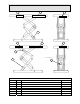
GENERAL MAINTENANCE Figure 14: Foot Switch Wiring Details – 115VAC/Single Phase Figure 15: Push Button Wiring Details – 115VAC/Single Phase 32
GENERAL MAINTENANCE Figure 16.
REPLACEMENT PARTS LIST Foot Switch Figure 17.
REPLACEMENT PARTS LIST 16 16 Figure 18.
REPLACEMENT PARTS LIST ITEM # DESCRIPTION 1 2 3 4 5 6 7 8 9 Base Frame Assembly Top Frame and Platform Assembly Lower Outer (stabilizer) Leg Assembly Upper Outer (stabilizer) Leg Assembly Lower Inner (lifter) Leg Assembly Upper Inner (lifter) Leg Assembly Roller Bearing Assembly Leg Pivot Bolt Assembly Center Axle Bolt Assembly 11 12 13 14 15 16 17 18 19 20 21 22 23 Outer Leg Hinge Bolt Assembly Inner Leg Hinge Assembly Cylinder Crosshead Assembly Cylinder Base Pin Assembly Hydraulic Cylinder Velocity
TROUBLESHOOTING ANALYSIS DANGER! To avoid personal injury, NEVER go under the lift platform until the load is removed and the scissors mechanism is securely blocked in the open position. See "Lift Blocking Instructions" section. WARNING! To avoid serious injury or death, GUARDS, INTERLOCKS, and SAFETY DEVICES must be restored to correct operation when installing parts or making repairs. PROBLEM Lift raises, then lowers back slowly. Lift lowers very slowly.
TROUBLESHOOTING ANALYSIS PROBLEM Lift does not raise. POSSIBLE CAUSE AND SOLUTION The motor rotation for a 3-phase motor may be reversed. Reverse only two motor electrical leads. Check for a line or hose leak. Check for oil shortage in the reservoir. Add oil as necessary (See Oil Requirements in the “Routine Maintenance” section.) The load may exceed the rating. (See the “Specifications” section.) Remove the excess load. The suction screen may be clogged, starving the pump.
TROUBLESHOOTING ANALYSIS PROBLEM Lift won’t lower. POSSIBLE CAUSE AND SOLUTION The solenoid coil may be incorrectly wired, burned out, not rated for the voltage, or the line voltage may be excessively low. Check voltage near the coil. The velocity fuse may be locked. Do not attempt to remove the velocity fuse. The following steps should be followed: 1. Remove the load from the lift. Inspect all fittings, hoses, and other hydraulic components for leads or damage. 2.
TROUBLESHOOTING ANALYSIS PROBLEM Lift seems bouncy during operation. Motor labors or heats excessively. POSSIBLE CAUSE AND SOLUTION Lower the lift to collapsed position and continue to hold “DOWN” button an additional 10-30 seconds to bleed air from the cylinder. Do not confuse spongy or jerky operation with small surges that may occur when operating on rough or uneven floors Check for oil starvation. The voltage may be low.
LIMITED WARRANTY The user is solely responsible for using this equipment in a safe manner and observing all of the safety guidelines provided in the Operation Manual and on the warning labels provided with the lift. If you are unable to locate either the manual or the warning labels, please contact Autoquip or access www.autoquip.com for replacement downloads or information.