INSTALLATION, OPERATION AND SERVICE MANUAL BASCULE BRIDGE SINGLE LEAF & DOUBLE LEAF P.O. Box 1058 • 1058 West Industrial Avenue • Guthrie, OK 73044-1058 • 405-282-5200 • FAX: 405-282-8105 • www.autoquip.com Item # 830BB Version 1.
TABLE OF CONTENTS Identification & Inspection 3 Dangers, Warnings, and Cautions 4 Safety Features 7 Label Identification 8 Specifications 12 Blocking Instructions 13 Installation Instructions 14 Operating Instructions 26 Routine Maintenance 28 General Maintenance 30 Replacement Parts List 40 Troubleshooting Analysis 41 IMPORTANT Please read and understand this manual prior to installation or operation of this equipment.
INSPECTION IDENTIFICATION When ordering parts or requesting information or service on this lift, PLEASE REFER TO THE MODEL AND SERIAL NUMBER. This information is on a nameplate attached to the lift platform. Replacement parts are available from a local Autoquip distributor. INSPECTION Immediately upon receipt of the lift, a visual inspection should be made to determine that the lift has not been damaged in transit. Any damage found must be noted on the delivery receipt.
DANGERS, WARNINGS & CAUTIONS SAFETY ALERTS (Required Reading!) The following SAFETY ALERTS are intended to create awareness of owners, operators, and maintenance personnel of the potential safety hazards and the steps that must be taken to avoid accidents. These same alerts are inserted throughout this manual to identify specific hazards that may endanger uninformed personnel. Identification of every conceivable hazardous situation is impossible.
DANGERS, WARNINGS & CAUTIONS Read and understand this manual and all labels prior to operating or servicing the bridge. All labels are provided in accordance with ANSI Z535.4. DANGER! To avoid personal injury, stand clear of the bridge and handrails while it is in motion. DANGER! HIGH VOLTAGE!! Disconnect and/or lock out the electrical supply to the power unit prior to any maintenance being performed.
DANGERS, WARNINGS & CAUTIONS WARNING! Under circumstances should the flow control be modified or removed from the pump or Deltatrol to obtain faster lowering speed. A loaded lift can reach dangerous and destructive speed and/or unnecessary closing of the velocity fuses. WARNING! NO RIDERS when the bridge is in motion. CAUTION! Become familiar with this manual before operating this equipment. CAUTION! Use only approved oils. Section.
SAFETY FEATURES HYDRAULIC VELOCITY FUSES Each hydraulic cylinder has a hydraulic velocity fuse (HVF) installed in the cylinder port. These HVFs are installed in the predetermined hydraulic oil flow velocity as the oil returns to the reservoir. They do not affect incoming oil. Should a catastrophic rupture or breach occur in the hydraulic system and oil flows through the breach that exceeds the HVF rating, the HVF will trigger and lock up.
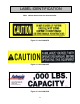
LABEL IDENTIFICATION 7 2 4 6 1 3 5 1 2 5 Figure 1 Label Placement Bascule Bridge Item No. Qty Description 1 3 Caution: Do not go under Lift Platform 36400679 2 3 Caution: Familiarize Yourself With Operators Manual 36401487 3 2 Capacity 36401602 4 2 Caution: Stay Clear of Lift Mechanism 36403046 5 3 Warning: No Riders 36403707 6 2 Warning: Stay Clear While Platform is Tilting 36403830 7 1 Autoquip Serial Number Nameplate 36401511 8 Part No.
LABEL IDENTIFICATION Note: Labels shown here are not actual size.
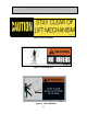
LABEL IDENTIFICATION Figure 5 Label 36403046 Figure 6 Label 36403707 Figure 7 Label 36403830 10
LABEL IDENTIFICATION Figure 8 Label 36401511 11
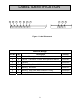
SPECIFICATIONS Model Plat. Width (feet) Face to Face of Cutouts (inches) 6 16 BB-1 BB-2 BB-3 BB-4 BB-5 BB-6 BB-7 BB-8 BB-9 BB-10 BB-11 BB-12 BB-13 BB-14 BB-15 BB-16 BB-17 BB-18 BB-19 BB-20 BB-21 BB-22 BB-23 BB-24 BB-25 BB-26 BB-27 BB-28 BB-29 BB-30 BB-31 BB-32 BB-33 BB-34 BB-35 BB-36 BB-37 BB-38 BB-39 BB-40 17 18 19 20 8 16 17 18 19 20 Load Cap.
BLOCKING INSTRUCTIONS DANGER! NEVER go under the bridge or perform maintenance until the load is removed and the bridge is securely blocked. 1. Lower the empty bridge platform into the horizontal position. 2. Place temporary supports under all corners of the bridge frame. 3. Drive shims and/or blocks between the bridge frame and the supports to relieve pressure from the lifting cylinders. 4. To remove temporary supports, hydraulically raise the bridge to the vertical position.
INSTALLATION INSTRUCTIONS DANGER! NEVER go under the bridge until the load is removed and the bridge is securely blocked. See “Blocking Instructions” section in this manual. BRIDGE (See Figures 9 through 13) 1. Set the bridge in the correct horizontal position (on “horses” or temporary welded supports). Line up accurately with the dock and hinge channel. NOTE: Hinge channel and clevis channel MUST be set plumb, square, and parallel by the pit contractor. 2.
INSTALLATION INSTRUCTIONS CAUTION! Precaution should be taken to prevent the introduction of contaminates such as dirt or other foreign material into the system through open fittings, pipes, or disassembled components. Contamination will ruin the hydraulic system. 9. Connect the power unit to the lift and safety leg cylinders. Refer to the hydraulic schematic in the Maintenance Section of this manual. Pipe that is used must be Schedule 80 with extra heavy fittings.
INSTALLATION INSTRUCTIONS CAUTION! Never unbolt the clevises or try to change the shims when the bridge is not resting solidly in its fully lowered position. 15. Check the fluid level in the reservoir and replenish if necessary. See the fluid specifications in the Maintenance Section of this manual. Cycle the bridge to set the limit switch tripping locations. NOTE: Initial limit switch settings should prevent over travel of the safety legs and bridge, or damage may occur. 16.
____" HINGE CHANNEL LENGTH 26" 22" 18" 12" Figure 9 Single Leaf Bascule Bridge – Plan View 15 1/4" 24" CUTOUT 3" x 3" x 1/4" THK. CURB ANGLES BY PIT CONTRACTOR. TYPICAL BOTH ENDS ___" NON - SKID STEEL PLATE PIT MOUNTED POWER UNIT FOR POWER UNIT MOUNTED UNDER BRIDGE ON THE CUTOUT, INSTALL ONLY THE (2) CONDUITS. (2) 3/4" CONDUITS. (1) FOR CONTROL & (1) FOR POWER. STANDARD SPACING OF RAMS ___" WILL PERMIT INSTALLATION OF POWER UNIT ON THE 24" MIN. CUTOUT IF DESIRED.
8" 35 1/2" CL REMOTE POWER UNIT (2) 3/8" EXTRA HEAVY GALVANIZED PIPES (1) 1/2" EXTRA HEAVY GALVANIZED PIPE 24" MIN. CUTOUT SHIM AS REQ'D. TO EQUALIZE BRIDGE AND DOCK HEIGHT. LIFTING CYLINDERS WITH CHROME PLATED RODS AND VELOCITY FUSES. _____" PLATFORM DEPTH CHECK RAILROAD CLEARANCES REQ'D FROM THIS POINT TO CENTER LINE OF TRACK. (TYP. BOTH ENDS.) 15 1/4" 16" MIN.
____" CLEVIS CHANNEL LENGTH AND DOCK OPENING 22" 18" 12" 24" CUTOUT 15 1/4" 2" CLEARANCE 26" STANDARD SPACING OF RAMS ___" WILL PERMIT INSTALLATION OF POWER UNIT ON THE 24" MIN. CUTOUT IF DESIRED. ___" BRIDGE #1 CONCRETE SUPPORT IF CLEARANCE ALLOWS 3" x 3" x 1/4" THK. x 24" LG. CURB ANGLES BY PIT CONTRACTOR. TYPICAL BOTH ENDS OPTIONAL AUTOMATIC FOLDING LEGS NON - SKID STEEL PLATE HYDRAULIC POWER UNIT PLACEMENT WHEN MOUNTED ON 24" CUTOUT.
8" 35 1/2" CL 24" MIN. CUTOUT 45" BRIDGE #2 6" HIGH WHEEL CURBS ON BOTH BRIDGES, BOTH SIDES 16" MIN. 3/4" CLEARANCE HINGE REACTION = _______ Lbs. PLUS DESIRED SAFETY FACTOR ______" (___' - _____") BRIDGE LENGTH _____" PLATFORM DEPTH _____" (___' - ___") FACE TO FACE OF HINGE CHANNELS LIFTING CYLINDERS WITH CHROME PLATED RODS AND VELOCITY FUSES. AUTOMATIC FOLDING LEGS BRIDGE #1 CHECK RAILROAD CLEARANCES REQ'D FROM THIS POINT TO CENTER LINE OF TRACK. (TYP. BOTH ENDS.) 15 1/4" 16" MIN.
INSTALLATION INSTRUCTIONS GRIND TOP SMOOTH AFTER FIELD WELDING BY INSTALLER. 16" MIN. HINGE REACTION HINGE CLEVISES SUPPLIED BY AUTOQUIP. (14) HINGES TOTAL. 10" x 20.0 LB. CHANNEL. W/ #5 REINFORCING BARS NO SUBSTITUTION BY AUTOQUIP. (INSTALLATION BY PIT CONTRACTOR) 20" MIN. Figure 13 Bridge Hinge Clevis Detail (4) 3/4"-10 UNC BOLTS WITH LOCKWASHERS PER CYLINDER CLEVIS. USE APPROPRIATE LENGTH BOLTS. CYLINDER CLEVIS PRE-DRILLED AND WELDED. FURNISHED BY AUTOQUIP.
INSTALLATION INSTRUCTIONS WEATHERPROOF JCT. BOX FOR POWER & CONTROL WIRING (BY INSTALLER) 24" CUTOUT 1/4" LINES FOR SAFETY LEGS. AUTOQUIP SUPPLIES (2) 1/4" HYDRAULIC WIRE BRAID HOSES. INSTALLER TO CONNECT & DRESS HOSES TOWARDS CENTERLINE OF BRIDGE. 29 1/4" REMOVABLE WEATHERPROOF COVER FACE OF DOCK JUNCTION BOX 23" 1/2" LINE FOR LIFTING CYLINDERS PUMP MOTOR CL RESERVOIR RAM BOLTS FOR REMOVABLE COVER 22" WEATHERPROOF NEMA-4 JCT. BOX WITH LABELED LEADS.
INSTALLATION INSTRUCTIONS BRIDGE IN RAISED POSITION RECESSES COMPLETLY INTO 24" CUTBACK (TYP. EACH BRIDGE) PIT MOUNTED POWER UNIT (2) 3/4" CONDUITS, (1) FOR POWER AND (1) FOR CONTROL (TYPICAL BOTH ENDS) REMOTE POWER UNIT (2) 3/8" (SCH. 80) BLACK PIPES AND FITTINGS, TO SAFETY LOG CYLINDERS. (TYPICAL BOTH ENDS) (1) 1/2" (SCH. 80) BLACK PIPE AND FITTINGS TO CYLINDERS. (TYP. BOTH ENDS) 3/4" CLEARANCE 35 1/2" 8" CL 16" MIN. 15 1/4" 24" MIN.
INSTALLATION INSTRUCTIONS UP: PRESSING THE "UP" BUTTON WILL CAUSE THE PUMP MOTOR TO START AND THE BRIDGE TO RAISE. AS THE BRIDGE APPROACHES VERTICAL AND THE SAFETY LEGS CLEAR THE CURB ANGLE, THE SAFETY LEGS WILL BE POWERED OUT. WHEN THE SAFETY LEGS ARE FULLY EXTENDED, THE POWER UNIT IS AUTOMATICALLY SHUT OFF. THE "UP" PUISHBUTTON CAN BE RELEASED AT THIS TIME. DOWN: PRESSING THE "DOWN" PUSHBUTTON WHEN THE BRIDGE IS UP WILL CAUSE THE PUMP MOTOR TO START MOMENTARILY.
ELECTRICAL JUNCTION BOX BGIDGE HINGES BRIDGE SAFETY WING SAFETY WING CYLINDER BRIDGE POSITION LIMIT SWITCH BRIDGE EXTENDED LIMIT SWITCH BRIDGE RETRACTED LIMIT SWITCH INSTALLATION INSTRUCTIONS Figure 18 Bascule Bridge Safety Leg Detail (Sheet 2)
OPERATING INSTRUCTIONS Familiarize yourself with this operator’s manual before operating the equipment!!! The Bascule Bridge has a maximum capacity rating (See the “Specifications” section). The safety relief valve should not be adjusted for any reason as it could cause the motor to prematurely burn out. Applying loads exceeding the rated capacity of the bridge may result in permanent damage.
OPERATING INSTRUCTIONS Down Pushbutton Pressing the “DOWN” pushbutton momentarily changes the signal to an “UP” signal through the safety legs fully retracted limit switches. The signal energizes the motor starter causing the bridge to rise slightly. At the same time, the “DOWN” pushbutton energizes the safety legs retract solenoid “B” through the motor starter auxiliary contact, causing the safety legs to be powered inward.
ROUTINE MAINTENANCE Normally the Bascule Bridge will require very little maintenance. However, a routine maintenance program could prevent costly replacement of parts and/or downtime. DANGER! To avoid personal injury, NEVER go under the bridge or perform any maintenance until the load is removed and the bridge is securely blocked. See "Blocking Instructions" section. MONTHLY INSPECTION: 1. Check oil level (see oil recommendations in this section) and add appropriate oil when necessary. 2.
ROUTINE MAINTENANCE Oil Viscosity Recommendations Environment (Ambient Temperatures) Recommended Oil Indoor location, variable temperatures (30 - 100° F) 10W30 or 10W40 Multiviscosity motor oil Indoor location, consistent Temperatures (70° F) SAE-20W motor oil Outdoor location, (-10 - 100° F) SAE 5W30 Multiviscosity motor oil Cold-storage warehouse (10 - 40° F) 5W30 Multiviscosity motor oil Freezer (-40° F to 0° F) Consult Factory OIL CAPACITY: Reservoir capacity for the steel tank is approximat
GENERAL MAINTENANCE 1. Change oil once a year or when it materially darkens or feels gritty. Also, check oil for the presence of water (oil will turn milky in color.) 2. NEVER TRY TO DISASSEMBLE OR REPAIR A PUMP IN THE FIELD. These pumps are high-precision devices requiring extreme precision in fit-up. When one is damaged, there is seldom anything that can be repaired in the field. It is also more economical to replace a pump than to refit old parts with new parts.
GENERAL MAINTENANCE POWER UNIT DANGER! HIGH VOLTAGE!! Disconnect and/or lock out the electrical supply to the power unit prior to any maintenance being performed. 1. The power unit utilizes a heavy-duty 5 HP/208, 230, or 460 Volts/60 hertz/3 phase motor coupled to a high-pressure positive displacement gear pump, and Autoquip Corporation’s patented Deltatrol valve assembly 2. The following should be referenced in connecting the standard heavy-duty motors to power sources.
GENERAL MAINTENANCE 7. Using a face spanner wrench, turn the bearing assembly clockwise until the tip of the retainer appears in the slot in the outer surface of the cylinder tube. 8. Insert a small blade screwdriver under the tip of the retainer and turn the bearing assembly counter-clockwise until the retainer is free of the slot. NOTE: The wire retainer may be a cutting or puncturing hazard. 9. Pull the rod out of the tube slowly to remove the rod and bearing assembly.
GENERAL MAINTENANCE 20. Turn the electrical supply back on and press the “UP” button on the controller to raise the bridge. NOTE: 15 to 30 seconds time may elapse to fill the empty cylinders before movement is noted. 21. Press the “DOWN” button on the controller to cycle the lift to the fully lowered position. Hold the “DOWN” button 30 to 40 seconds to allow air in the cylinders to bleed back into the reservoir tank. 22.
GENERAL MAINTENANCE PISTON WEAR RING LOCK NUT SEAL RETAINING RING FOAM RING WEAR RING O-RING O-RING WIPER HEAD ROD ASS'Y TUBE ASS'Y Figure 19 Hydraulic Cylinder 34
GENERAL MAINTENANCE VELOCITY FUSE REPLACEMENT DANGER! Do not attempt to remove the velocity fuse until the bridge is securely supported with the blocking devices and all hydraulic pressure has been removed from the lifting cylinders and hydraulic hoses. Failure to follow these instructions could result in personal injury or death! Never attempt to take a velocity fuse apart and repair it. These are precision devices that are factory assembled under exacting conditions.
GENERAL MAINTENANCE ROCK SALT It has been discovered that rock salt is being used to melt the ice and snow off of the platforms in the northern region and during the winter months. Rock salt will accelerate the deterioration of any paint. Therefore, Autoquip recommends the use of a synthetic “Ice Melt” product in lieu of rock salt. Warranty on the paint finish will be denied when it is suspected that rock salt has been used.
PUMP MOTOR M 37 SUCTION LINE FILTER PUMP FIXED DISPLACEMENT HYDRAULIC WIRE BRAID HOSES FROM CYLINDERS TO OIL LINE. FURNISHED BY AUTOQUIP. CONNECTED BY INSTALLER. HYDRAULIC CYLINDERS WITH CHROME PLATED ROD, CLEVIS MOUNTING. QUANTITY DEPENDS ON SPECIFIC MODEL. RESERVOIR RELIEF VALVE (PRESET AT AUTOQUIP) CHECK VALVE T P COMPLETE OIL INFORMATION WILL BE IN BASCULE BRIDGE INSTALLATION MANUAL PROVIDED AT TIME OF BRIDGE DELIVERY. OIL BY INSTALLER. DOWN SOL. VALVE DOWN SOL.
13 18 12 17 2 7 3 2 2 2 2 2 UP PUSHBUTTONS STA. #1 STA. #2 8 4 5 14 9 DOWN PUSHBUTTONS STA. #1 STA. #2 GROUND SUPPLY VOLTAGE 19 6 6 L1 11 #2 AUX. CONTACT ON MAG. STARTER 11 DOWN SOL. RET. SOL. "B" SAFETY LEG SFETY LEGS EXTEND SOL.
GENERAL MAINTENANCE Figure 22 Pushbutton Assembly 39
REPLACEMENT PARTS LIST POWER UNIT PARTS LIST QTY Vertical Description Part No.
TROUBLESHOOTING ANALYSIS DANGER! To avoid personal injury, NEVER go under the bridge or perform any maintenance until the load is removed and the bridge is securely blocked. See "Blocking Instructions" section. PROBLEM Bridge does not raise. POSSIBLE CAUSE AND SOLUTION • • • • • • • • • • • Bridge seems bouncy during operation. The motor voltage/wiring may be incorrect. The hydraulic line or hose may be leaking. Oil in the reservoir may be low.
TROUBLESHOOTING ANALYSIS PROBLEM Bridge will not lower. POSSIBLE CAUSE AND SOLUTION • • • • • The down solenoid may be malfunctioning. The structural members may be in a bind. The tubing or hose is obstructed or broken. Check for obstruction in the line. The return filter may be clogged. The velocity fuse may be locked. Do not attempt to remove the velocity fuse. The following steps should be followed: 1. Inspect all fittings, hoses, and other hydraulic components for leads or damage. 2.
TROUBLESHOOTING ANALYSIS PROBLEM Bridge raises slowly. Bridge lowers slowly. POSSIBLE CAUSE AND SOLUTION • The structural members of the bridge may be binding. • The tubing or hose is obstructed or broken. Where pipe is used, check for obstruction in the line. • The hydraulic line or hose may be leaking. • The oil viscosity is not suited for the environmental conditions. Refer to “Routine Maintenance” section for oil recommendations. • Check the oil level in the reservoir.
TROUBLESHOOTING ANALYSIS PROBLEM Bridge will not remain in raised position. POSSIBLE CAUSE AND SOLUTION • The cylinder packing may be leaking. • The pump or Deltatrol regulator is not seating. • The pump or Deltatrol check valve is not seating. • The hydraulic tubing, hose, or fitting is leaking oil. • The return filter may be clogged.