
Installation Manual

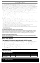


A
C EDB F G
Hydrofarm.com
6
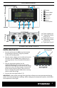
ZONE A OUTPUT SCHEDULE
The PX2 lets you precisely schedule up to six
med output sengs from the xtures during
the light cycle (by waage or percentage).
Checkmarks in front of the six med output
sengs provide the ability to disable or enable.
CHECK = Enabled.
1. Press
and enter the ZONE A OUTPUT
SCHEDULE menu.
2. Press
to cursor through the me and
output sengs.
3. Press
or
to adjust, then press
buon to conrm.
4. Repeat steps 2–3 to set all values.
5. Press
buon to save the sengs.
6. Repeat steps for ZONE B.
IMPORTANT ZONE OUTPUT SCHEDULE NOTES
• Output adjustments ONLY take eect according to OUTPUT SCHEDULE and clock seng.
• Enabling more OUTPUT SCHEDULE sengs is advisable for greater exibility.
• Sunrise and sunset (R/S) me seng can impact OUTPUT SCHEDULE. Ensure these two
sengs do not conict. Example: If R/S is set to 10 minutes, the ming between OUTPUT
SCHEDULE signals should be set no less than 10 minutes.
INSTRUCTIONS
Indicator Meaning
A, C
LED on green: Normal status. Screen display: NML
LED on yellow: Over-temperature dimming protecon. Screen display: DIM
LED ashes red: Over-temperature lamp-o protecon or temperature exceeds 80°C.
Screen display: SOS
LED ashes yellow: Temperature control line is not inserted. Screen display: NO PROBE
B, D
LED LIGHT ON: Lamp on. LED LIGHT OFF: Lamp o.
E
If the ANALOG indicator is on, the controller outputs 0–10V signals for LED, 0–11.5V for HID.
F
If the DIGITAL indicator is on, the controller outputs RS485 signals.
E, F
The ANALOG and DIGITAL indicators are both on.
ZONE A is the analog signal output, and ZONE B is the digital signal output.
G
The output signal mode can be switched by clicking the SET buon with a pen.
LED INDICATORS