
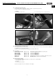
Operating instructions

Zuleitung, 230V~
77
3 x 1,5mm²,
KWL EC 700 D Pro (WW), KWL EC 800 S Pro (WW)
85233 002 SS-1006 13.02.13
M
24V~/
0-10V=
1
1
Bedienelement
RJ12
R
J12
6
Signal V
entilator an,
(potentialfr
eier Kontakt) !
88
Exter
ne Heizung, W
asserpumpe,
(Pr
o und WW) max. 230V~/2A
66
Fortluft - V
erschlussklappe, 230V~
exter
ne Komponente
1010
99
Feueralarm,
exter
nes Signal,
p
otentialfr
eier Kontakt !
33
Heizung bei
WW-T
ype,
WW-Register
inter
n,
Mischer exter
n
24V/0-10V
9
GND
M
1~
Signal der Sicherheits-
e
inrichtung, siehe
MBV-Montage und
Betriebsvorschrift
Optional:
B
auseits bei
R
aumluft-
abhängigen
Feuerstätten
zu erstellen !
L1 N PE
Optional:
Bauseitiger
On/off switch
Trennschalter /
VDE 0700 T1 7.12.2
L1
N
PE
2
2
15V~
GND1
CO2
24V~
0-10V
55
Außenluft - V
erschlussklappe, 230V~
exter
ne Komponente
N
open/auf
230V~
230V~
N
open/auf
230V~
230V~
10
31
32
33
34
35
36
38
N
230V~
41
42
Kondensat Schwimmerschalter
,
exter
nes Signal,
p
otentialfr
eier Kontakt !
43
44
Exter
nes Signal,
p
otentialfr
eier Kontakt !
45
46
max. 50m
44
1111
Klemmleiste Platine
Platine
250V~
2A /AC1
UX1
GND2
GND2
W
W-Type
M
24V~/
0-10V=
33
Mit WW Heizung
ohne WW-T
ype,
WW-Register
exter
n,
Mischer exter
n
24V/0-10V
11
GND
0-10V
12
oder
24V~
KWL EC-CO
Art.Nr. 9988
2
A1
GND
15-24V~
/ 24V=
~~
+
-
RJ
KWL EC-FF
Art.Nr. 9989
A1
GND
15-24V~
/ 24V=
~~
+-
RJ
A2
GND
15V~
GND1
CO2
GND2
24V~
0,2A
~
~
B
eispiel
Helios-WHSH Type 24V/0-10V (SS-956)
24V~/ 0-10V=
~~
+
0-10V
U
1235
24V~
GND2
9
10
11
12
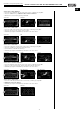
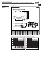
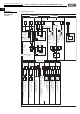
7.0 Wiring diagram SS-1006
fig.31
28
Central ventilation units KWL EC 700/1400/2000 D Pro / WW
Installation and operating instructions
CHAPTER 7
WIRING DIAGRAM
O
VERVIEW
UK
Outside air – cover flap, 230V~
external components
Exhaust air – cover flap, 230V~
external components
Signal Ventilator on,
(Potential-free contact) !
External heater, Water pump
(Pro and WW) max. 230V~/2A
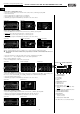
Fire alarm,
external signal,
Potential-free contact!
Condensation float switch,
external signal,
Potential-free contact!
external signal,
Potential-free contact!
Supply line
Controller
Terminal block
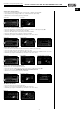
Heater for
WW-Type,
WW-heater
internal,
Mixer external
24V/0-10V
With WW-heater
without WW-Type,
WW-heater
extern,
Mixer external
24V/0-10V
or
Example
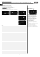
O
ptional:
on-side
isolator /
Optional:
To be establis-
hed on-side for
heat systems
t
hat depend
o
n room air.
Safety system signal,
see installation and
operating instructions!
Circuit board
Circuit board