
Operating instructions
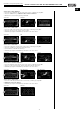
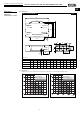
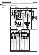

5.0 Dimensions
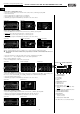
5.1 Adjustment
Adjustment of flow rate characteristic curves by type with details on recommended ventilation range:
23
Central ventilation units KWL EC 700/1400/2000 D Pro / WW
Installation and operating instructions
Z
JK
[
ÈòHH
^
]
_
\
`
a
Y
X
W
c
d
b
Wx|
p|
WÊ{|
\|
Wy~òò{
Dim. in mm
KWL EC 700/1400/2000 D Pro
KWL EC 700 D Pro / WW
Recommended:
Basic ventilation range
Nominal ventilation range
Intensiv ventilation range
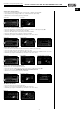
KWL EC 1400 D Pro / WW
Recommended:
Basic ventilation range
Nominal ventilation range
Intensiv ventilation range
V
·
m
3
/h
∆p
fa
Pa
∆p
fa
Pa
V
·
m
3
/h
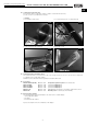
fig.12
Reverse side
Front
Dim. in mm A B C D E F G H I J K L M ø N
KWL EC 700 D 1418 840 957 336 359 175 213 398 230 224 324 872 900 10
KWL EC 1400 D 1718 1280 1397 424 399 195 295 610 375 274 524 1312 1200 10
KWL EC 2000 D 2018 1600 1717 523 489 240 345 770 485 324 624 1632 2x700 10
CHAPTER 5
DIMENSIONS
C
HARACTERISTIC CURVES
UK
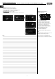
View from below
Extract air
Outside air
Exhaust air
Supply air