
Operating instructions

20
Central ventilation units KWL EC 700/1400/2000 D Pro / WW
Installation and operating instructions
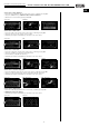
Service menu 7: Temperature sensor
1. Select the “Temperature sensor“ function in the service menu, confirm by pressing “OK“
2. Select “Control“ key
3. Select “Supply air“ key, supply air sensor is activated
4. Select “Extract air“ key, extract air sensor is activated
5. Confirm by pressing the “RETURN“ key and return to the service menu
Service menu PID values
Servicemenü Kalibrierung
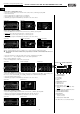
Service menu 8: Offset ventilators
1. Select the “Offset Vent.“ function in the service menu, confirm by pressing “OK“
2. Supply air:
Press arrow keys and increase or decrease speed
3. Extract air: Press arrow keys and increase or decrease speed
4. Confirm by pressing the “RETURN“ key and return to the service menu
Service menu Supply
air speed setting Extract air speed setting
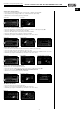
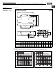
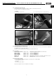
Service menu 9: Function test
Various control parameters (sensors, ventilators etc.) can be tested in real-time in this menu.
The function test must be carried out by a specialist, so that the controls and/or the unit is not
damaged!
1. Select the “Function test“ function in the service menu, confirm by pressing “OK“
2. Press the “+“ or “-“ key or “Flap/Run“ key to set the desired parameter
(refer to symbol explanation on right)
3. Press on “Display field“ to return to the service menu
Service menu Function test display Function test
Service menu 10: External sensor
1. Select the “External sensor“ function in the service menu, confirm by pressing “OK“. The following exter-
nal sensors can be activated: CO
2
sensor (CO
2
), humidity sensor (RH) and mixed gas (VOC)
2. Select the desired external sensor
3. Confirm by pressing the “RETURN“ key and return to the service menu
Service menu External sensor
Service menu 11: Bypass settings
1. Select the “Bypass settings“ function in the service menu, confirm by pressing “OK“
2. Increase or decrease the outside air limit temperature with the arrow keys
3. Confirm by pressing the “RETURN“ key and return to the service menu
Service menu Outside air limit
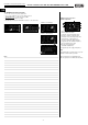
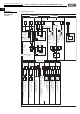
Function test – Symbol explanation:
1. Supply air ventilator
2. Extract air ventilator
3. Pre-heating
4. Post-heating
5. Bypass
– Temperature sensor
6. Extract air > Int. 1
7. Outside air > Ext. 1
8. Exhaust air temp. > Int. 2: -4 °C
9. Supply air temp. in the air supply duct > Ext. 3:
+29 °C
10. Supply air temp. in the ventilation unit > Ext. 2
13. Flow rate Supply air ventilator
14. Flow rate Exhaust air ventilator
– Accessories
11. Relay test cover flap
(1=open / 0=closed)
12. Relay test device 1=ON / 0=OFF
☛
➧➧
☛
➧
➧
☛
➧
➧
☛
☛
☛
☛
☛
➧
☛
☛
➧
☛
☛
1111
1122
77
66
11 22 33 44 55
➧
Note: Values in Pos. 6 to 10 cannot be changed!
UK
1100
99
88
1133
1144