
Operating instructions

deviation will be detected by the control and the ventilation unit will begin to reduce the flow rate until the desired con-
stant pressure is reinstated. The resulting flow rate will distribute to the respective residential units corresponding to the
ventilation ductwork planning.
Constant pressure means static pressure in the duct network. In case of changes in pressure in the duct network (e.g.
by opening and closing flaps), the set constant pressure (target value) is achieved by regulating the airflow rate (reduc-
tion or increase of the ventilator speed).
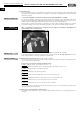
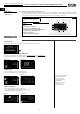
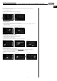
3.2.15 Automatic bypass
– What is the function of Automatic bypass in your ventilation unit?
The main function of Automatic bypass is not to channel the fresh outside air through the heat exchanger, but rather
through the so-called “bypass channel” in the unit past the heat exchanger and directly into the supply air rooms.
Terminology:
Bypass closed: Outside air is channelled through heat exchanger into the room = Active heat recovery
Bypass open: Outside air is channelled through heat exchanger into the room = Active heat recovery
Outside air is channelled directly into the room = Inactive heat recovery, indirect “cooling“ of room air.
– When is the unit bypass used?
The bypass is normally used in the summer months for so-called “night cooling“. With regard to night cooling. the effect
of cool outside temperatures is used in comparison to room or inside temperatures.
The bypass can also be used in transition periods (spring and autumn) if the room temperature is significantly higher
than the outside air temperature during the day due to high windows (“natural bypass cooling“).
The night cooling effect and “natural bypass cooling“ is strongly influenced by the temperature differences between
outside air/supply air and room air, the flow rate, the shade and the required cooling loads. Bypass cooling will never
replace air conditioning!
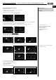
–Bypass functional description
If the ventilation unit is supplied with system voltage, the bypass will close completely. The bypass will open if the all of
the following conditions are met:
Condition 1: The room temperature is higher than the set target supply air temp. (factory setting: 21 °C)
Condition 2: The outside air temperature is higher than the set outside air temperature limit (factory setting: 15 °C).
The temperature of the outside air temperature limit, can be changed on the controller > Service menu:
“Bypass settings“ (see also Page 20).
Condition 3: The room temperature is higher than the outside air temperature.
The bypass is closed if one of the aforementioned conditions is no longer met!
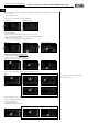
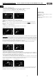
3.2.16 Demand-driven regulation of ventilation units through CO
2
- and humidity sensors
The ventilation unit has the connection option for a sensor (CO
2
or humidity). The sensor is connected directly to the
unit motherboard pursuant to the wiring diagram.
The CO
2
controller monitors the CO
2
-concentration in the room and ensures increased ventilation at higher concentra-
tions to prevent, for example, signs of fatigue, the lack of concentration or headaches. The CO
2
sensor is deactivated
on the service menu of the controller when delivered from the factory.
The humidity controller ensures increased ventilation at higher levels of indoor humidity (% r.F.) for the removal of moi-
sture to counteract damage to the building material. The humidity controller is deactivated when delivered from the fac
tory.
In order to activate the sensor controller, the CO
2
-sensor or humidity sensor must be activated on the service menu >
“Ext. sensor“ (see also Page 20) of the controller after connection to the motherboard.
Furthermore, the ventilation unit must be operated in “Monozone“-mode and “Automatic-mode“ (settings on service
menu > “Ventilation mode“ (see also Page 18), to set the desired CO
2
limit value (factory setting 1000 ppm) or desired
humidity limit value (factory setting 50 % r.F.).
The unit airflow rate is controlled automatically depending on the CO
2
concentration or the relative humidity. The airflow
rate is automatically increased with the increase of the respective sensor value. If the set limit value is exceeded, the
ventilation unit will work at max. flow rate capacity.
3.2.17 Vent calibration
The maximum operating point of the ventilation unit is determined during ventilator calibration. in this respect, the ven-
tilation unit runs at 100% ventilator capacity for a defined period of time. The maximum achievable flow rate and the
corresponding static pressure in the ductwork is shown as a result of the ventilator calibration.
The calibration can be activated on the controller > Service menu 2: “Vent calibration“ (see also Page 19).
The calibration takes around 3-5 minutes!
In the context of starting up and adjustment of the ventilation unit, the ventilator calibration must be carried
out before adjusting the ventilation unit! All control dampers should be pre-set to the desired target value, all
valves should be completely opened.
12
Central ventilation units KWL EC 700/1400/2000 D Pro / WW
Installation and operating instructions
NOTE
☞
ATTENTION
UK