
Operating instructions

11
Central ventilation units KWL EC 700/1400/2000 D Pro / WW
Installation and operating instructions
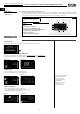
3.2.6 Thermal comfort temperature
Condition I: Supply air temp. (sensor EXT3) is less than +16,5 °C
Condition II: Outside air temp. (sensor EXT1) is less than -10 °C
The pre-heater will be controlled corresponding to the difference to achieve a constant supply air temperature.
3.2.7 Cover flaps, 230V~ for outside and exhaust air (to be provided on site)
The cover flaps which are to be provided on site prevent cold draughts in case of faults or when the unit is switched off.
Faults include:
- Frost-protection of hot water heater
- Frost-protection of heat exchanger (step 3)
A cover flap must be mounted in the outside and exhaust air for the KWL EC .. PRO WW (internal hot water
heater) to prevent frost damage to the heater or heat exchanger.
3.2.8 RUN output
The RUN output can, for example, serve as a signal for building control systems to determine the system status. A relay
output is located on the unit (label: “RUN“) and as soon as the KWL unit is in ventilation mode, the contact is closed.
3.2.9 External contact (signal)
The KWL unit can be put into standby mode or ventilation mode through the “External contact“ function.
– Contact open = Standby mode
– Contact closed = Ventilation mode
If the KWL unit is switched to ventilation mode via the controller > Service menu 10: “Ext. sensor“ (see also Page 20),
the external contact must first be closed and then opened to put the KWL into standby mode. This is also the case if
the KWL unit has been put into standby mode via the controller. The external contact must first be opened and then
closed to put the KWL into ventilation mode.
3.2.10 Fire mode (fire contact)
The KWL unit can be put into two operating modes (exhaust air mode or
standby mode) through the “Fire mode“ function (Fire contact):
– “Unit off“ (Standby)
– “Extract air“
These modes can be selected from the controller > Service menu 14: “Fire mode“ (see also Page 21). If the fire contact
is opened, the previously selected operating mode will be activated.
The controller will be locked during this time.
3.2.11 Condensate contact
Condensate contact is an error message "condensation tub overflow" on the controller. The ventilators will be shut
down. Function is not required!
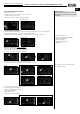
3.2.12 Monozone “manual“
"Monozone" / "CAV" = Operate the ventilation unit in constant airflow mode.
This function can be selected on the controller > Service menu 1: “Ventilation mode“ (see also Page 18).
If it is necessary to operate the ventilation unit at a desired flow rate, the operating mode "Monozone“ / “CAV" is recom-
mended. The desired flow rate is then set directly on the main menu by pressing the “Flow rate value“ on the display.
3.2.13 Monozone „auto“
The ventilation unit can also be operated in Automatic mode "Monozone“ / “CAV"-mode.
– Condition: Sensor must be activated (Service menu 10).
Automatic mode can be selected on the controller > Service menu 1: “Ventilation mode“ (see also Page 18).
Press "M" key. The unit will switch to Automatic mode which is indicated with an "A". Depending on the connected and
activated sensors, it is also possible to enter a “limit value (ppm)“ for the respective sensors. When the limit value is rea-
ched, the ventilation unit will operate at the max. power available.
The ventilation unit therefore increases or decreases the flow rate capacity before reaching the limit value depending on
the target/limit value comparison. Pressing the "A" symbol again switches the unit back to the “manual“ ventilation
mode ("M" symbol).
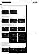
3.2.14 Multizone
"Multizone" / "VAV" = Operate the ventilation unit in the constant pressure mode
The mode can be selected on the controller > Service menu 1: “Ventilation mode“ (see also Page 18).
Enter "Multizone“ / “VAV"-mode by pressing "Monozone". The current “flow rate (m
3
/h)“ is shown on the display (can-
not be changed), as well as the current set “constant pressure value (Pa)“. The desired constant pressure value can be
increased or decreased by pressing the +/-key. The minimum constant pressure value is limited to 20 Pa.
Some ventilation applications require the use of the ventilation unit in constant pressure mode (“Multizone“ /“VAV“-
mode). The "constant pressure" operating mode is typically selected if the ventilation unit is to ventilate different
zones/units (Multizone) with variable flow rate requirements.
In an apartment building, six residential units are ventilated with a central ventilation unit. Each of the residential units
can vary the flow rate by controlling a valve. In this case, the technical planner will normally calculate a constant pres-
sure for nominal flow rate for the ventilation ductwork. If a valve is then closed, the static pressure in the ventilation duc-
twork will change at a constant flow rate and cause a deviation from the calculated and set constant pressure. The
IMPORTANT NOTE
☞
UK
EXAMPLE
☞