
Operating instructions

3.2 Functions
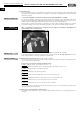
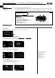
3.2.1 Internal pre-heater
According to criteria for passive houses, a pre-heater is mandatory to prevent the Cross counter flow heat exchanger
from freezing! The pre-heater is located behind the outside air filter F7.
– Detailed pre-heated regulation:
The pre-heater will be active if the following conditions are met:
Condition I: Outside air temperature (sensor EXT1) less than - 4 °C
Condition II: Exhaust air temperature (sensor INT2) less than + 0 °C
Condition III: Pre-heater is not deactivated in menu section (12 Pre-heater)
If all conditions are met, the pre-heater will be controlled corresponding to the difference to achieve a constant out-
going air temperature.
The pre-heater will be deactivated if the following conditions are met:
Condition I: Outside air temperature (sensor EXT1) is more than -3 °C
or
Condition II: Exhaust air temperature (sensor INT2) is more than +4 °C
Important note:
The pre-heater only activates if the supply air ventilator is extracting the minimum flow rate and there are no errors. If
the KWL unit is switched to standby mode, the supply air ventilator will run for 60 seconds in case the pre-heater was
activated before that. If the pre-heater before this and, for example, the KWL unit is switched to standby 20 seconds
later, the supply air ventilator will then only run for 40 seconds.
General information on the pre-heater
The pre-heater is equipped with two safety temperature limiters, the STL (auto reset = trigger temp. +50 °C) and
(manual reset = trigger temp. +120 °C) are connected in series. Once a safety temperature limiter is triggered, the pre-
heater will be disconnected from the power supply and an error will be displayed on the controller.
3.2.2 Heat exchanger frost-protection
The heat exchanger frost-protection function is divided into 3 steps:
Step I: Pre-heater activation (see section 3.1.1)
Step II: Reducing the flow rate / Exhaust and supply air ventilator
Condition I: Pre-heater has been switched on for longer than 3 minutes
Condition II: Exhaust air temperature (sensor INT2) is less than 0 °C
If both conditions are met, the exhaust and supply air ventilator will reduce by 50 %, however, not more than 50 % of
the total flow rate. The pre-heater will not be deactivated in this period.
Step III: Emergency shutdown Supply air ventilator
Condition I: The flow rate of the exhaust and supply air ventilator is reduced for longer than 5 minutes
or
Condition II: The pre-heater is deactivated.
AND
Condition III: Exhaust air temperature (sensor INT2) is less than 0 °C
If the conditions are met, the pre-heater will be deactivated and the supply air ventilator will be shut down.
The Heat exchanger frost-protection will be deactivated if the following conditions are met:
Condition I: Outside air temperature (sensor EXT1) is more than -3 °C
or
Condition II: Exhaust air temperature (sensor INT2) is more than +4 °C
If the conditions are met, the heat exchanger frost-protection will be deactivated.
9
Central ventilation units KWL EC 700/1400/2000 D Pro / WW
Installation and operating instructions
NOTE
☞
IMPORTANT NOTE
☞
UK