Helios Ventilatoren INSTALLATION AND OPERATING INSTRUCTIONS Nr.
ENGLISH This product contains batteries or accumulators. According to the German Battery Act (BattG), we are obliged to point out the following: Batteries and accumulators must not be disposed of in household waste. You are legally obligated to return used batteries and accumulators. You can return batteries to a community collection point or return them to the place where you bought them free of charge.
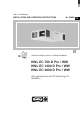
Installation and operating instructions Central ventilation units KWL EC 700/1400/2000 D Pro / WW UK Table of Contents CHAPTER 1. GENERAL INSTALLATION AND OPERATING INSTRUCTIONS . . . . . . . . . . . . . . . . . . . . . . . . . . . .page 2 1.0 Important information . . . . . . . . . . . . . . . . . . . . . . . . . . . . . . . . . . . . . . . . . . . . . . . . . . . . . . . . . . . . . . . . . .page 2 1.1 Warning and safety instructions . . . . . . . . . . . . . . . . . . . . . . . . . . . . . . . . . . .
Installation and operating instructions Central ventilation units KWL EC 700/1400/2000 D Pro / WW UK 1.0 Important information CHAPTER 1 To ensure safety and correct operation please read and observe the following instructions carefully before proceeding. Important information is specified in the maintenance section on filter changes and necessary cleaning and maintenance activities. The user usually accomplishes maintenance work.
Installation and operating instructions Central ventilation units KWL EC 700/1400/2000 D Pro / WW UK 1.8 Function and operation modes The KWL units are equipped with one or more cross counter flow heat exchangers, in which the heat of the extracted air is recovered and transferred through the plates to the incoming fresh external air, so both air flows remain separated. Through this procedure more than 80 % of the extract air heat is transferred to the external air.
Installation and operating instructions Central ventilation units KWL EC 700/1400/2000 D Pro / WW UK 1.11 Technical data KWL EC 700 D Pro Voltage/Frequency Rated current – ventilation Rated current – pre-heating Max.
Installation and operating instructions Central ventilation units KWL EC 700/1400/2000 D Pro / WW UK 2.0 CHAPTER 2 INSTALLATION NOTE ☞ Important note: 1. The ventilation ducts must not become kinked. 2. The connections to the connection valves must be firm and tight. 3. The terminal box is connected to the side of the casing and must be easily accessible for maintenance and installation work. 4.
Installation and operating instructions Central ventilation units KWL EC 700/1400/2000 D Pro / WW UK 2.2 Condensation outlet The humidity of exhaust air condenses to water during the heating period. A lot of condensate can build up in new buildings with large numbers of people. The condensate water collected in the condensate tub made of stainless steel is discharged via a ball siphon (not included in scope of delivery). An incline of at least 3° (Fig.
Installation and operating instructions Central ventilation units KWL EC 700/1400/2000 D Pro / WW UK WARNING 2.5 Unit insulation If installed in heated rooms and higher humidity, condensation can occur on the outside of the unit in the outside and extract air area. In this case, water-vapour-tight insulation is to be installed on the surface in this area. Furthermore the outside and exhaust air ductwork should be insulated sufficiently. If installed in unheated areas (e.g.
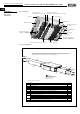
Installation and operating instructions Central ventilation units KWL EC 700/1400/2000 D Pro / WW UK CHAPTER 3 3.0 Unit overview Hot water heater (Type KWL EC ...D Pro WW) Hot water connection for WHSH... (Type KWL EC ...D Pro WW) FUNCTIONAL DESCRIPTION Bypass (not visible) Casing Isolator Terminal box F5-Extract air filter Condensation outlet Ø 22mm F7-Outside air filter EC-high performance ventilator – supply air Elec.
Installation and operating instructions Central ventilation units KWL EC 700/1400/2000 D Pro / WW UK 3.2 Functions 3.2.1 Internal pre-heater According to criteria for passive houses, a pre-heater is mandatory to prevent the Cross counter flow heat exchanger from freezing! The pre-heater is located behind the outside air filter F7.
Installation and operating instructions Central ventilation units KWL EC 700/1400/2000 D Pro / WW UK 3.2.3 Hot water heater A hot water heater ensures the comfortable and energy-efficient post-heating of supply air. This is particularly useful if the supply air (heated outside air from the heat exchanger) is to be heated to a higher temperature level (normally room temperature or higher). KWL EC .. Pro WW ATTENTION ☞ – Connection and regulation of internal hot water post-heater (only Type KWL EC ..
Installation and operating instructions Central ventilation units KWL EC 700/1400/2000 D Pro / WW UK 3.2.6 Thermal comfort temperature Condition I: Supply air temp. (sensor EXT3) is less than +16,5 °C Condition II: Outside air temp. (sensor EXT1) is less than -10 °C The pre-heater will be controlled corresponding to the difference to achieve a constant supply air temperature. 3.2.
Installation and operating instructions Central ventilation units KWL EC 700/1400/2000 D Pro / WW UK deviation will be detected by the control and the ventilation unit will begin to reduce the flow rate until the desired constant pressure is reinstated. The resulting flow rate will distribute to the respective residential units corresponding to the ventilation ductwork planning. Constant pressure means static pressure in the duct network. In case of changes in pressure in the duct network (e.g.
Installation and operating instructions Central ventilation units KWL EC 700/1400/2000 D Pro / WW UK Note: 13
Installation and operating instructions Central ventilation units KWL EC 700/1400/2000 D Pro / WW UK 4.0 CHAPTER 4 Surface-mounted controller with touch screen The central ventilation unit is controlled with a surface-mounted controller (Fig. 11). It enables freely definable operating levels within the total performance curve range, a weekly or daily programme as well as other features. The controller comes with a control line (5 m) with a double sided RJ 12 plug for easy installation as standard.
Installation and operating instructions Central ventilation units KWL EC 700/1400/2000 D Pro / WW UK 5. Set time and day of the week Important note: Setting the time and day of the week is essential for creating a functional weekly programme 1. Press the “Time“ key 2. Set time and day of the week using the or arrow keys 3. Confirm entry by pressing “OK“ OR: Return to the main menu by pressing “RETURN“ Time/day of the week ➧ ☛ 6.
Installation and operating instructions Central ventilation units KWL EC 700/1400/2000 D Pro / WW UK Once the individual settings are complete, the programmed switching times and parameters can be displayed in an overview. 1. Press the “Overview“ key 2. Return to the weekly menu by pressing “RETURN“ Daily/weekly menu Overview time intervals ➧ ☛ ☛ Copy time intervals 1. Press the “Overview“ key 2. Press the “Copy“ key. The displayed day of the week is copied. 3.
Installation and operating instructions Central ventilation units KWL EC 700/1400/2000 D Pro / WW UK Once the individual settings are complete, the programmed switching times and parameters can be displayed in an overview. 1. Press the “Overview“ key 2. Return to the weekly menu by pressing “RETURN“ Daily/weekly menu Overview time intervals ➧ ☛ ☛ 7. Temperatures 1. Press the “Target temperature“ key in the main menu. 2.
Installation and operating instructions Central ventilation units KWL EC 700/1400/2000 D Pro / WW UK Service menu 1: Ventilation mode 1. Select the function “Ventilation mode“ in the service menu, confirm by pressing “OK“ 2. Select the ventilation mode: Monozone / CAV or Multizone / VAV 3. Confirm by pressing the “RETURN“ key and return to the service menu Service menu Ventilation mode: "Monozone" / "CAV" = Operate the ventilation unit in the constant airflow mode.
Installation and operating instructions Central ventilation units KWL EC 700/1400/2000 D Pro / WW UK Service menu 2: Vent calibration 1. Select the “Vent calibration“ function in the service menu, confirm by pressing “OK“ 2. Press the “Calibration“ key. Calibration takes around 3-5 minutes! 3. Return to the service menu by pressing “RETURN“ Service menu ☛ Calibration ☛ ➧ ➧ Service menu 3: PIN control 1. Select the “PIN control“ function in the service menu, confirm by pressing “OK“ 2.
Installation and operating instructions Central ventilation units KWL EC 700/1400/2000 D Pro / WW UK Service menu 7: Temperature sensor 1. Select the “Temperature sensor“ function in the service menu, confirm by pressing “OK“ 2. Select “Control“ key 3. Select “Supply air“ key, supply air sensor is activated 4. Select “Extract air“ key, extract air sensor is activated 5.
Installation and operating instructions Central ventilation units KWL EC 700/1400/2000 D Pro / WW UK Service menu 12: Pre-heating 1. Select the “Pre-heating“ function in the service menu, confirm by pressing “OK“ 2. Select “On“ (Factory setting) or “Off“ key to activate/deactivate pre-heating 3. Return to the service menu by pressing “RETURN“ Service menu Pre-heater ➧ ☛ ☛ Service menu 13: External post-heating 1.
Installation and operating instructions Central ventilation units KWL EC 700/1400/2000 D Pro / WW UK 10. Additional service function 1. Press the “Service“ key in the main menu 2. Access the additional service menu with password: Password: 1717 > confirm by pressing “OK“ 3. Overview (see description on right) 4. Confirm by pressing the “RETURN“ and return to the main menu Additional service function – Symbol explanation 6 KWL EC ...Pro unit display Servicemenü 3 4 9 1 Vorheizung ☛ ➧ ☛ ➧ KWL EC .
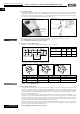
Installation and operating instructions Central ventilation units KWL EC 700/1400/2000 D Pro / WW UK 5.0 Dimensions fig.12 KWL EC 700/1400/2000 D Pro DIMENSIONS CHARACTERISTIC CURVES W Front Extract Wx| air X b Y Outside air WÊ{| Exhaust \ |air Supply p|air View fromò{ below Wy~ò Reverse side c d ÈòHH ^ _ ` ] \ [ CHAPTER 5 a JK Z Dim.
Installation and operating instructions Central ventilation units KWL EC 700/1400/2000 D Pro / WW UK ∆pfa Pa KWL EC 2000 D Pro / WW Recommended: Basic ventilation range Nominal ventilation range Intensiv ventilation range V· m3/h NOTE ☞ 5.2. Minimum requirements for starting up The start-up is carried out through a system calibration. “Vent-calibration“ (see also Page 20) is activated on the controller > Service menu 2: and the system starts the system characteristic curve.
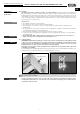
Installation and operating instructions Central ventilation units KWL EC 700/1400/2000 D Pro / WW UK ATTENTION ☞ 3. Fold condensation tub downwards (Fig. 15) Tub may contain condensation water! 4. Pull the frost protection sensor WT from the heat exchanger fins (Fig. 16) fig.15 WARNING fig.16 Support heat exchanger in doing so! 5. Loosen all screws from the heat exchanger fastener (Fig.17) 6. Carefully pull cross counter flow heat exchanger from the unit (Fig.18) fig.17 fig.
Installation and operating instructions Central ventilation units KWL EC 700/1400/2000 D Pro / WW UK – Filter The KWL compact unit is equipped with fine filters on the outside and extract air side as standard (pursuant to DIN EN 13779): • Outside/exhaust air: Air filter F5 Extract air 1St. ELF-KWL 700 D/5 No. 4189 Air filter F7 Supply air 1St. ELF-KWL 700 D/7 No. 4191 ELF-KWL 700 D/5 VDI No. 4190 ELF-KWL 700 D/7 VDI No. 4192 Air filter F5 Extract air 1St. ELF-KWL 1400 D/5 No.
Installation and operating instructions Central ventilation units KWL EC 700/1400/2000 D Pro / WW UK 6.4 Condensation outlet in the unit Ensure that the lateral condensation outlet (ø 22 mm) is secured above the base tray (see also section 2.2) for maintenance measures. – Cleaning 1. Condensation outlet nozzles 2. Loosen fastening screws on condensation tub fig.27 3. Fold condensation tub downwards fig.28 4. Clean with a cloth fig.29 fig.30 6.
85233 002 SS-1006 13.02.13 28 KWL EC-FF Art.Nr.
85234 002 SS-1007 13.02.13 29 1 5 x 1,5mm² 9 10 2 ~~ + 46 11 12 Example Beispiel Helios-WHSH Type 24V/0-10V (SS-956) With WW-heater Mit WW Heizung ohne WW-Type, WW-Type, without WW-Register WW-heater extern, extern, Mischer extern Mixer external 24V/0-10V 24V/0-10V 0,2A 0-10V ~ ~ 24V~ 45 KWL EC-FF Art.Nr.
KWL EC-FF Art.Nr. 9989 5 x 2,5mm² 85235 002 SS-1008 13.02.
31 yellow black brown blue black brown Unlined Unlined Outside air flap Exhaust air flap Siganl fan on potentia-free contact Alarm Heating Heater for WW Type, WW-heater internal, Mixer external 0-10V With WW-heater without WW-Type, WW-heater extern, Mixer external 24V/0-10V Outside air sensor Pre-heater External fire alarm Heat exchanger sensor External alarm condensate External siganl Supply air sensor Extract air sensor Sensor input Exhaust air sensor Sensor Hot water Sensor Water alarm with
32 yellow black brown Exhaust air motor Supply air motor Outside air flap Exhaust air flap Siganl fan on potentia-free contact Alarm Heating Heater for WW Type, WW-heater internal, Mixer external 0-10V With WW-heater without WW-Type, WW-heater extern, Mixer external 24V/0-10V Outside air sensor Pre-heater External fire alarm Heat exchanger sensor External alarm condensate Supply air sensor External siganl Extract air sensor Sensor input Exhaust air sensor Sensor Hot water Sensor Water alarm withe
33 yellow black brown Exhaust air motor Supply air motor Outside air flap Exhaust air flap Siganl fan on potentia-free contact Alarm Heating Heater for WW Type, WW-heater internal, Mixer external 0-10V With WW-heater without WW-Type, WW-heater extern, Mixer external 24V/0-10V Outside air sensor Pre-heater External Heat exchanger fire alarm sensor External alarm condensate Supply air sensor External siganl Extract air sensor Sensor input Exhaust air sensor Sensor Hot water Sensor Water alarm withe w
All pictures without guarantee! Please keep this manual for reference with the unit! Print-No.: 82 600/03.13 www.heliosventilatoren.