
Installation manual

C3 RS915 REV. A
2
TABLE OF CONTENTS:
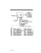
INSTALLATION DIAGRAMS 4
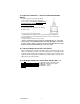
H1: 6 PIN HEAVY GAUGE WIRING CONNECTION 6
H1/1 Violet Wire – Starter Output 6
H1/2 & H1/3 Red Wire – +12V Power Input 7
H1/4 Yellow Wire – Ignition 1 Output 7
H1/5 Pink Wire – Ignition 2 Output 7
H1/6 Brown Wire – Accessory Output (Heater /ACC Output) 7
H5: 5 PIN WHITE WIRE HARNESS 8
H5/1 Red / White wire – Parking Light Relay Power Input 8
H5/2 White wire – Parking Light Relay Output 8
H5/3 Black wire – System Ground 8
H
5
/4 Brown wire
–
Siren Drive Output
8
H
5
/5 Red wire
–
System Power
8
H
7
: 4
-
PIN BLACK CONNECTOR TWO
-
WAY TRANSCEIVER/ANTENNA MODULE
9
H8. 2 PIN BLUE CONNECTOR FOR THE VALET SWITCH 9
H3. 2 PIN WHITE CONNECTOR FOR THE LED STATUS INDICATOR 9
H9. 4 PIN ORANGE CONNECTOR FOR 2 STAGE SHOCK SENSOR (ZONE 1/4) 10
H6: 22 PIN WIRE CONNECTOR 10
H2 C3 SERIAL DATA PORT CONNECTION RS -232 Port 16
H4. 3 PIN DOOR LOCK CONNECTOR (maximum 500 mA output) 17
Negative Trigger Door Lock System 17
Positive Trigger Door Lock System 17
Alternating Door Lock System 17
Vacuum Operate Door Locking System 17
2 Steps Door Unlock Wire Connection-5 Wires Alternating Lock System 18
2 Steps Door Unlock Wire Connection- (-) Switched Door Lock System 18
2 Steps Door Unlock Wire Connection- (+) Switched Door Lock System 18
PROGRAMMING & TESTING:
PROGRAMMING THE REMOTE TRANSMITTER 19
FEATURES PROGRAMMING 19
Alarm Feature “A” Programming 19
Alarm Feature “B” Programming 20
Alarm Feature
“C”
Programming
22
Channel 4 Timer Control Output Programming
23
Password Pin Code Setup
24
Start Feature “D” Programming 24
Start Feature “E” Programming 25
Tachometer Checking Type – RPM Learning & Testing 26
Voltage Checking Type – Start Timer Set-up & Testing 27
Timer Checking Type – Start Timer Set-up & Testing 28
Test Mode 28
RETURN TO FACTORY DEFAULT SET TING 29
TROUBLE SHOOTING 30
SHUTDOWN DIAGNOSTICS 30
TESTING YOUR INSTALLATION 30
Test the Brake shutdown circuit 31