
User manual


Getting Started
ZonePRO™ User Manual
2
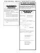
Section 1
ZonePRO
™
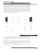
1. IEC Power Cord Receptacle
The ZonePRO 1260/1261 comes with a power supply that will accept voltages ranging from
100V-240V at frequencies from 50Hz-60Hz. An IEC cord is included.
2. S/PDIF Connection
This RCA connection is used to connect up to two digital input channels in the 1260/1261.
3. PC Connection (DB-9)
This DB-9 connection is used to communicate to the PC GUI and uses RS-232 protocol. This
connection requires a Null modem cable and one is included with the ZonePRO unit.
4. Ethernet Connection (RJ-45)
This RJ-45 connection is used to control the unit via Ethernet.
5. Zone Control Inputs 1-12 (RJ-45)
This input connection is used to send information and power to the ZC wall controllers.
6. Outputs Channels 1-6 (Euroblock)
The output section of the ZonePRO offers six electronically balanced Euroblock connectors.
7. Input Link Buss (RJ-45)
The ZonePRO offers an input buss that duplicates the first six inputs from one unit to the next
for applications requiring more than six output zones.
8. Input Source Channels 1-8 (RCA)
The input section of the ZonePRO offers eight mono-summing unbalanced RCA connectors.
9. Line/Mic Selector
This switch is used to select either the line or microphone input.
10. Signal/Clip LED
This LED is used to indicate microphone signal input or clip.
11. Mic/Line Inputs 1-2 (Euroblock)
The input section of the ZonePRO provides two Euroblock connectors for mic/line inputs.
12. Mic Gain Control
This knob is used to set the input gain for the microphone input.
1.1 - Rear Panel (1260 and 1261)