
Specifications


74
Variable Frequency Drive Units
The combination variable frequency AC motor drive units contain a high performance,
microprocessor-controlled, variable frequency AC drive and either a fusible
disconnect switch or a circuit breaker.
They also:
•Include isolated logic and power.
•Include fans and venting where required.
•Include internal electronic overload protection.
•Include EMC filters on 380…415V AC.
•Include UL Class CC (PowerFlex 40 drives) or J time delay fuses. These fuses provide
both branch circuit protection and drive input protection. The drive input fuses are
provided in series with the circuit breaker in some drive units.
• Include control circuit transformer (CCT). The CCT is sized to provide power for all standard pilot devices and any
required fans.
• Produce a three-phase, pulse width modulated (PWM) adjustable frequency output and voltage output for
exceptional control of motor speed and torque.
• Are digitally programmable with access to mode programming, providing precise and repeatedly accurate setup,
control and operation and adaptability to handle a variety of applications.
• Have available 24V DC or 115V AC control voltages on some units.
You will need to select a Human Interface Module (HIM) and Control Platform Type for the drive units.
Select the drive unit based on nominal load HP(kW) size. If full load current exceeds ouitpout current, select the unit based
on the next larger HP(kW).
Drives listed as Normal Duty have output current overload capabilities are 110% for 60 seconds and 150% for 3 seconds.
Drives listed as Heavy Duty have output current overload capabilities are 150% for 60 seconds and 200% for 3 seconds.
Each unit is provided as a NEMA Wiring Class I, Type A unit with terminals mounted on the drive chassis for connection of
remote pilot devices and input signals. For NEMA Type 3R and NEMA Type 4 enclosure construction, contact your local
Rockwell Automation Sales Office or Allen-Bradley distributor.
Proper placement of drive units in the MCC is essential for proper operation and life cycle of the drive. Strong
consideration should be given to placing units with drives at the bottom of the section. When more than one drive unit is
placed in a section, the drive unit with the highest rating should be located at the bottom of the section.
Do not mount transormer units below drive units. Heat from the transformer units may cause the drive to trip.
For additional information regarding variable frequency drives refer to the PowerFlex Low Voltage Drives Selection Guide,
publication PFLEX-SG002
.
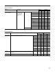
For PowerFlex 40 drive unit selection go to page 75
.
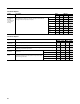
For PowerFlex 70 drive unit selection go to page 76
.
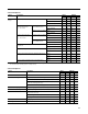
For PowerFlex 700 drive unit selection go to page 79
.
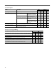
For PowerFlex 753 drive unit selection go to page 83
.
For variable frequency drive unit options go to page 88
.