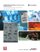
CENTERLINE® 2100 Motor Control Centers Selection Guide Industry-Leading Motor Control Centers Delivering Safety, Performance and Reliability
CENTERLINE® 2100 Motor Control Centers Selection Guide Product Overview. . . . . . . . . . . . . . . . . . . . . . . . . . . . . . . . . . . . . . . . . . . . . . . 2 Selection Process. . . . . . . . . . . . . . . . . . . . . . . . . . . . . . . . . . . . . . . . . . . . . . . . 8 Technical Details. . . . . . . . . . . . . . . . . . . . . . . . . . . . . . . . . . . . . . . . . . . . . . . . 9 IntelliCENTER® Technology. . . . . . . . . . . . . . . . . . . . . . . . . . . . . . . . . . . . 10 ArcShield™. .
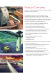
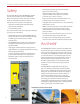
Product Overview Industry-Leading Motor Control Centers Delivering Safety, Performance and Reliability The CENTERLINE 2100 Motor Control Center (MCC) combines rugged durability and premium quality, meeting UL and NEMA standards. CENTERLINE 2100 MCCs integrate control and power in one centralized package with a wide variety of motor control options. This industry-leading motor control center has delivered the safety, performance and reliability you need for over 35 years.
Space Saving Units Space savings With limited floor space in your facility for motor control equipment, space saving units can help reduce your section count and save valuable floor space. Space saving unit designs for CENTERLINE 2100 MCCs are available for Size 1-5 full voltage non-reversing and Size 1-3 full voltage reversing starter units, feeder units, drive units and soft starter units.
Industry-Leading Motor Control Centers Delivering Safety, Performance And Reliability IntelliCENTER® Technology CENTERLINE Motor Control Centers (MCCs) with IntelliCENTER technology use intelligent motor controls, built-in networking and pre-configured and tested software to enhance performance through system-wide communications that share diagnostic information for predictive maintenance and initiate warnings before potential faults occur.
Increase Uptime with Advanced Maintenance Tools The preconfigured software gives maintenance personnel easy access to critical CENTERLINE MCC configuration information and process data for troubleshooting. The configurable system views give you system status at a glance and can help keep facilities running with electronic documentation, remote diagnostics and predictive maintenance.
Industry-Leading Motor Control Centers Delivering Safety, Performance And Reliability Safety • Continuous bus bracing provides more uniform support than point bracing The standard offering of the CENTERLINE 2100 MCC provides you with improved safety. CENTERLINE MCCs are designed to enhance operation and make it safer.
“The safety issue is one of the things that we are happiest with. The old system created hazardous troubleshooting conditions, with technicians having to test and probe and work around live wires within a confined panel space.
Industry-Leading Motor Control Centers Delivering Safety, Performance And Reliability Selection Process Select a CENTERLINE 2100 Motor Control Center Select Technology Select Structure Select Power Systems Select Unit Designs Select Unit Types 8 Choose the type of networking technology, diagnostic and HMI software tools and additional arc flash safety features Choose the NEMA enclosure, section height, depth, wireway size and type of shutters Choose electrical system, incoming power, power and groun
CENTERLINE® 2100 Motor Control Centers The CENTERLINE 2100 Motor Control Center (MCC) combines rugged-durability and premium quality, meeting UL and NEMA standards. CENTERLINE 2100 MCCs integrate control and power in one centralized package with a wide variety of motor control options. The industry leading motor control center that has delivered the safety, performance and reliability you need for over 35 years.
IntelliCENTER Technology Built-in Networking • Media protected behind barriers • Access ports in wireways • Trunk and drop topology allows for addition and removal of devices without shutting down the network Intelligent Motor Controls • • • • PowerFlex® drives SMC™-3 and SMC™ Flex soft starters E1 Plus, E3 Plus electronic overload relays DeviceNet Starter Auxiliaries IntelliCENTER Software • • • • Elevation View Monitor View Documentation View Spreadsheet View Factory Configuration • Network media val
DeviceNet Cable Layout The DeviceNet trunk line is routed through the vertical wireway of the MCC. DeviceNet Trunk Line Trunk lines are routed behind barriers to isolate the cable from the unit space and wireways to help prevent accidental damage. Up to six DeviceNet ports can be provided in the control and network wireway. Each DeviceNet component in an MCC unit is connected to the network through a port located in the wireway.
IntelliCENTER Software The CENTERLINE 2100 MCC is available with pre-configured IntelliCENTER software. IntelliCENTER software is an intuitive software package that is customized to your MCC. This software package includes several preconfigured views for easy access to important information and is capable of viewing multiple MCC line-ups. IntelliCENTER software can be installed and operated on EtherNet/IP, ControlNet or DeviceNet.
Spreadsheet View The spreadsheet view allows you to access MCC data such as: • Node number (network address) • Unit description • Nameplate data • Device type Event Log View The event log records and stores events with date and time information occurring within your MCC and stores them with their date and time. Events can include device warnings and faults as well as parameter or device changes.
Testing IntelliCENTER technology can save you time because each MCC is pre-wired and the network is pre-programmed and validated at the factory. Network devices are pre-configured with node addresses and communication rates, ready to communicate so you can configure device parameters (for example, acceleration time and full load amps) via the network. For more information on MCCs with DeviceNet, refer to CENTERLINE Motor Control Centers with DeviceNet, publication 2100-TD019.
Notes: 15
ArcShield CENTERLINE 2100 Motor Control Center with ArcShield is an enhanced version of the industry-leading CENTERLINE 2100 MCC and is the first and only NEMA low voltage MCC to offer an arc resistant design. CENTERLINE 2100 MCC with ArcShield provides enhanced personnel protection and reduced exposure to arc flash hazards per IEEE C37.20.7-2007, IEEE Guide for Testing Metal-Enclosed Switchgear Rated up to 38 kV for Internal Arcing Faults.
ArcShield Features Insulating covers on horizontal bus closing plate Manual or automatic shutters Pressure relief system (100 ms arc duration rating only) Arc-resistant latches on all doors Arc-resistant rating label Horizontal and vertical ground bus system Arc-resistant baffles (for device limited arc resistant rating only) ArcShield 100 ms arc duration rating only Vertical angles at each end of MCC Polycarbonate baffles at each end of lineup ArcShield 100 ms arc duration rating only Reinforced bac
Structure The CENTERLINE 2100 Motor Control Centers structure consists of sections, wireways, doors and plug-in or frame mount units. CENTERLINE 2100 MCCs are listed by UL as complying with MCC Standard UL 845. Sections The rigid, free-standing sections are assembled individually. Shipping blocks are factory assembled from individual sections. Multiple section shipping blocks have continuous lifting angles, horizontal power bars, horizontal ground bus and internal mounting angle.
Bus Design CENTERLINE bus design means more current carrying capacity per section.
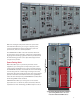
Section Construction Lift angle Top Horizontal Wireway Baffles Removable Top Plate Top Horizontal Wireway Pan Top End Closing Plate (two on 20” deep sections) Top Horizontal Wireway Cover Vertical Wireway (door closed) Right Unit Support Assembly (vertical wireway) Horizontal and Vertical Bus Support Bus Splice Access Cover ArcShield End Closing Plate Insulator Vertical-to-horizontal Bus Connection Center End closing plate Nameplate (serial nameplate shown) Vertical-to-horizontal Bus Connection Acc
Section Dimensions Section Dimensions The standard dimensions of a vertical section are 90 in. high x 20 in. wide x 15 in. deep (2286 mm x 508 mm x 381 mm). Vertical sections are also available as 20 in. deep (508 mm). Some vertical sections may be wider than 20 in. (508 mm) due to larger equipment or optional vertical wireway. Optional 71 in. (1791 mm) reduced height vertical sections are available. These sections can be either 15 in. (381 mm) or 20 in. (508 mm) deep and each 71 in.
Technical Data Standards Bus Material and Plating Unit Design Structural Surface Treatments Environment Certifications & Listings NEMA ICS-18, UL845, CSA C22.2 No.
Wireways Each MCC has horizontal and vertical wireways for continuous dedicated wire and cable location. Horizontal Wireways Continuous Horizontal Top Wireway Continuous Vertical Wireway Horizontal wireways are located at the top and bottom of each MCC section. Horizontal wireways extend the full width and depth of the MCC. The top and bottom are horizontal wireways 6 in. (152.4 mm) high. Complete wireway access from front to rear is available for back-to-back configured MCC sections.
Incoming Power CENTERLINE 2100 Motor Control Centers are designed for use on three-phase, three-wire or four-wire, Wye connected power systems, rated 600V or less, 50 or 60 Hz, with a solidly grounded neutral.
Vertical Power Bus Vertical power bus bars are cylindrical providing optimum contact with the unit plug-in stabs. Vertical power bus bars are continuously braced by a high strength, non-tracking glass polyester material and sandwiched by a glass filled polycarbonate molded bus cover isolating the vertical power bus from the other vertical phases and the horizontal power bus. The standard vertical power bus is a copper tube rated 300 A above and below the horizontal power bus for an effective 600 A rating.
Vertical Unit Load Ground Bus The vertical unit load ground bus is mechanically connected to the horizontal ground bus. The vertical unit load ground bus in combination with the unit load connector provides a termination point for the load ground cable at the unit. This fixed connection does not need to be removed when withdrawing the unit from the MCC. The 0.1875 in. x 0.750 in. (4.74 mm x 19.05 mm) vertical unit load ground bus can be unplated or tin-plated copper.
Space Factor Unit size is described in space factors. Units are designed in 0.5 space factor increments. Each 0.5 space factor is 6.5 in. (165.1 mm) high. Each standard, 90 in. high MCC section can contain 6.0 space factors. Up to twelve 0.5 space factor units can be placed in a section. Continuous Horizontal Wireway Continuous Vertical Wireway 0.5 Space Factor Unit 6.0 Space Factors Total 1.0 Space Factor Unit 2.
Unit Design Plug-in Unit Design Features Plug-in units consist of the unit, unit support pan and unit door. Plug-in units are held securely in the section when inserted and are designed with an interlock to help ensure that units cannot be inserted or withdrawn when the disconnect means is in the ON/I position. Frame Mounted Unit Design Features Unit Unit Door Unit Support Pan Frame mounted units are permanently mounted in the section, all connections are made directly to the components.
Stab Assembly The two-piece power stab housing is made of high strength, non-tracking glass polyester material and provides a separate, isolated pathway for each phase. The power cable connection at the plug-in stab is made with a maintenance free crimp style connection. There is no exposed wiring at the back of the unit between the disconnecting means and the plug-in stabs. Unit plug-in power stabs are rated 225 A.
Unit Types You can choose from a variety of units including contactor and starter units, metering units, main and feeder units, lighting and power panel units, transformer units, combination soft starter units, variable frequency AC motor drive units and programmable controller units. Catalog numbers and complete selection rules can be found in the CenterONE® configuration software or the CENTERLINE 2100 Motor Control Centers Catalog, publication 2100-CA001.
Combination Full Voltage Reversing Starter Units (FVR) - Bulletin 2106 and 2107 These combination full voltage reversing starter units are supplied with an Allen-Bradley Bulletin 505 reversing starter and either a fusible disconnect or a circuit breaker. The Bulletin 2106 and 2107 starters are rated for NEMA sizes 1 through 5 and are mechanically and electrically interlocked to avoid both contactors being closed simultaneously.
Space Saving NEMA Combination Full Voltage Reversing Starter Units (FVR) - Bulletin 2106 and 2107 These combination full voltage reversing starter units offer a space saving alternative while utilizing an Allen-Bradley Bulletin 300 reversing starter and either a fused disconnect or a circuit breaker. The Bulletin 2106 Space Saving NEMA reversing starters are rated for NEMA Size 1 applications and the Bulletin 2107 Space Saving NEMA reversing starters are rated for NEMA Size 1 through 3 applications.
Combination Full Voltage Non-reversing Starter Units (FVNR) - Bulletin 2112 and 2113 These combination full voltage non-reversing starter units are supplied with an Allen-Bradley Bulletin 509 starter and either a fusible disconnect or a circuit breaker. The full voltage non-reversing starters are rated for NEMA sizes 1 through 6. Each unit is provided as a NEMA Class I, Type B-T unit, with terminals mounted in the unit for connection to remote devices.
Combination Vacuum Full Voltage Non-reversing Starter Units (FVNR) - Bulletin 2112 and 2113 These combination full voltage non-reversing starter units are supplied with an Allen-Bradley Bulletin 1102C contactor and either a fusible disconnect or a circuit breaker. The full voltage non-reversing vacuum starters are rated 200 A, 400 A or 600 A. Each unit is provided as a NEMA Class 1, Type B unit, with terminals mounted in the unit for connection to remote devices.
Space Saving NEMA - Combination Full Voltage Non-Reversing Starter Units (FVNR) Bulletin 2112 and 2113 These combination full voltage non-reversing starter units offer a space saving alternative while utilizing an Allen-Bradley Bulletin 300 starter and either a fused disconnect or a circuit breaker.
Combination 2-Speed Starter Units (TS2W and TS1W) - Bulletin 2122E, 2123E, 2122F and 2123F These combination two-speed starter units are supplied with an Allen-Bradley Bulletin 520 starter and either a fusible disconnect or a circuit breaker. The 2122 and 2123 starter units are designed for use with motors having separate windings or consequent pole windings. The 2122E, 2123E, 2122F and 2123F are rated for NEMA sizes 1 through 5.
Notes: 37
Metering Units Metering Compartments - Bulletin 2190 Bulletin 2190 metering units are used for power management of three-phase systems and include analog ammeter and voltmeter, Powermonitor II and Powermonitor 3000 units. The ammeter, voltmeter, digital meter and Powermonitor 3000 units include a 30 A fused disconnect switch.
Notes: 39
Main and Feeder Units Outgoing Feeder Lug Compartment (FLUG) and Incoming Main Lug Compartment (MLUG) - Bulletin 2191F and 2191M Line lug compartments provide a lug connection for incoming lines (2191M) to distribute power to the CENTERLINE 2100 MCC or for outgoing cables (2191F) to feed power from the MCC to an external load. These line lug compartments are available with ratings from 300…2000 A. Optional mechanical or crimp lugs can be supplied with the lug compartments.
Lug Compartments for Inside Corner, 10” Wide Sections and Neutrals/Incoming Line and Outgoing Feeders Rating (Amperes) Cable Provisions Maximum Number Per Phase and Maximum Cable Size Space Factor(1) Mechanical Type Lugs Single Cable Lug Crimp Type Lugs INSIDE CORNER SECTION 600…2000 (4) 800 kcmil (4) 750 kcmil 6.0 (2) 750 kcmil (4) 500 kcmil 6.0 10” WIDE SECTION 600…1200 Not Applicable (1) Adding options may increase the space factor of the unit.
Feeder and Main Fusible Disconnect Switch Units (FDS, MFDS) - Bulletin 2192F and 2192M These switches are available with ratings from 30…2000 A. The 2192F is a plug-in unit for ratings up to 200 A and frame mounted for ratings 400 A and above. The 2192M is frame mounted (rigidly mounted and hardwired) in the structure for all ratings. The bolted pressure switch design is used for 2192 units rated 600…2000 A. Select disconnect switch rating based upon 125% of actual load amperes.
Feeder and Main Circuit Breaker Units (FCB, MCB) - Bulletin 2193F and 2193M Bulletin 2193F and 2193M are circuit breaker units with trip ratings available from 15…2000 A. These units are available with thermal magnetic trips up to 400 A and electronic trips 600 A and above. The 2193F is a plug-in unit for ratings up to 225 A and is a frame mounted unit for ratings 400 A and above. The 2193M is frame mounted for all ratings.
Bulletin 2193F 3-Pole Feeder Circuit Breaker (FCB), continued Frame Rating (Amperes) Type 600 LD 800 Range of Available Trips (Amperes) Interrupting Capacity Ratings (rms symmetrical Amperes) 208V/240V 65k 35k 25k 100k 65k 35k LDC 100k 100k 50k 400…800 HMDL NDC 1200 600V HLD MDL 300…600 380V/400V 415V/480V Space Factor(1) 65k 50k 25k 100k 65k 35k 100k 100k 65k 65k 50k 25k HND 100k 65k 35k NDC 100k 100k 65k ND 600…1200 2.0 2.5 3.
Bulletin 2193M 3-Pole Main Circuit Breaker (MCB), continued Frame Rating (Amperes) 800 1200 Type MDL Range of Available Trips (Amperes) 400…800 Space Factor(2) 208V/240V 380V/400V 415V/480V 600V 65k 50k 25k MDLG 65k 50k 25k HMDL 100k 65k 35k HMDLG 100k 65k 35k NDC 100k 100k 65k NDCG 100k 100k 65k MDL HI-MAG 800 42k 35k 22k ND 600…1200 65k 50k 25k 65k 50k 25k NDG 2000(1) Interrupting Capacity Ratings (rms symmetrical Amperes) HND 100k 65k 35k HNDG 100k 65k
Lighting and Power Panel Units Lighting Panel (LPAN) - Bulletin 2193LE Bulletin 2193LE is a frame mounted lighting panel with either a main lug or main circuit breaker. The lighting panels are rated for 100 A or 225 A with up to 42 branch circuits. One, two and three pole bolt-on branch circuit breakers are available with ratings from 15…100 A. Bulletin 2193LE Frame Mounted Lighting Panel for Bolt-on Branch Circuit Breakers (LPAN) Type Panel Bus and Main Lug Ampere Rating Max.
Panel Board with Main Circuit Breaker (PPAN) - Bulletin 2193PP Bulletin 2193PP is a plug-in unit panel board with a main circuit breaker. The panel boards are rated for 100 A, 150 A or 225 A with up to 42 branch circuits. One, two and three pole bolt-on branch circuit breakers are available with ratings from 15…100 A. The Bulletin 2193PP panel board is suitable for use with 3-phase, 4-wire, solidly grounded, Wye systems rated 480Y/277V or less.
Transformer Units Control and Lighting Transformers without Disconnecting Means (XFMR) - Bulletin 2195 Control and Lighting Transformers with Fusible Disconnect Switch (XFMR) - Bulletin 2196 Control and Lighting Transformers with Circuit Breaker (XFMR) - Bulletin 2197 The transformer units are available with ratings from 0.5…50 kVA for single-phase and 10…45 kVA for three-phase. Secondary fuses are provided with each transformer unit.
Control and Lighting Transformer Unit, continued Bulletin 2196 Space Factor(4) Bulletin 2196Z Space Factor(4) Bulletin 2197 Space Factor(4) Bulletin 2197Z Space Factor(4) 1.0 1.0 — 1.0 — 1 1.5 1.5 1.5 1.6 2.0 2.0 2.0 1.5 2.5 Rating kVA(1) Recommended Primary Protection (Amperes) 380V 400V 415V Bulletin 2195 Space Factor(4) SINGLE PHASE—110/115 Volt secondary with one 1-pole circuit breaker 0.5 15(2) 15(2) 15(2) 0.75 2 3 (1.5) 2.0 2.5 2.
Miscellaneous Units Full section blank mounting plates are six space factors in size. They are available with no disconnect means, fusible disconnect switch or circuit breaker. They are also available with or without the horizontal bus. Blank unit doors are available in a range of space factors from 0.5…4.0 in 0.5 space factor increments. The blank unit doors cover the unused unit space and have a unit support pan.
Miscellaneous Units Description NEMA Type “C” Terminal Board Unit (supplied unwired) Space Factor(2) Includes Bulletin 1492-CA1 terminal blocks Top or bottom-mounted 44 Terminal Blocks 1.0 66 Terminal Blocks 88 Terminal Blocks 110 Terminal Blocks Top or bottom-mounted 76 Terminal Blocks 1.5 114 Terminal Blocks 152 Terminal Blocks 190 Terminal Blocks Neutral Connection Plate Unit Surge Protective Device Unit (formerly known as TVSS)(1) 0.25 in. x 2 in. x 12 in.
Miscellaneous Unit Options Pilot Devices Option Push Buttons Description FVC FVR FVNR TS1W TS2W 2102L 2103L 2106 2107 2112 2113 2122 2123 Start - Stop Forward - Reverse - Stop High - Low - Stop Off Stop On - Off Fast - Slow - Stop Push Buttons and Selector Switch Hand-On, Hand-Off, Hand-Off-Auto Hand-Start, Hand-Stop, Hand-Off-Auto Control Station Housing Blank 1 hole—for one pilot device 2 holes—for two pilot devices 3 holes—for three pilot devices 4 holes—for f
Pilot Lights (Non-push-to-test and Push-to-test) Description FVC FVR FVNR TS1W TS2W 2102L 2103L 2106 2107 2112 2113 2122 2123 On On - Off Forward - Reverse Forward - Reverse - Off On On - Off High - Low Fast - Slow High - Low - Off Fast - Slow - Off High - Low - Forward - Reverse Fast - Slow - Forward - Reverse High - Low - Forward - Reverse - Off Fast - Slow - Forward - Reverse - Off Overload Control Circuit Transformer (with grounded and fused secondary) Desc
E1 Plus Electronic Overload Relay Option E1 Plus Electronic Overload Relay Description Selectable trip class (10, 15, 20, 30) selectable Auto/ Manual-Auto reset electronic overload relay for NEMA starters, Size 1-6.
E3 Electronic Overload Relay(1) Description E3 Basic is provided with two (2) 24V DC inputs and one (1) 110…240V AC output. FVR FVNR 2106 2107 2112 2113 NEMA size 1…6 Vacuum Contactor Starters E3 Plus is provided with four (4) 24V DC inputs and two (2) 110…240V AC outputs. NEMA size 1…5 NEMA size 6 Vacuum Contactor Starters E3 Plus with voltage protection and energy monitoring.
Miscellaneous Options Option Description FVNR 2112 2113 Blown Fuse Indicator Lights Option is valid only when 480V and 600V Power Factor Correction Capacitor is selected 480V and 600V Power Factor Correction Capacitors 2 kVAR through 40 kVAR in 0.5 space factor. 42.5 kVAR through 50 kVAR in 1.0 space factor. These capacitors should not be used on motors subject to plugging or jogging.
Miscellaneous Options Option Description Ground Detection Lights Three (3) Bulletin 800T pilot lights (clear), wired in grounded WYE, complete with fusing. 240 Volt 480 Volt 600 Volt 208 Volt FVC FVR FVNR TS1W TS2W 2102L 2103L 2106 2107 2112 2113 2122 2123 Available on Bulletin 2191M, 2192M and 2193M ONLY Not for use with solidly grounded power systems 415 Volt 400 Volt 380 Volt Three (3) Bulletin 800T push-to-test pilot lights (clear), wired in grounded WYE, complete with fusing.
Miscellaneous Options Option Description Rating Incoming Neutral Bus For Bulletins 2192M (main fusible disconnect switch) and 2193M (main circuit breaker). Provides for incoming neutral connection to horizontal neutral bus within the main incoming unit. Incoming neutral bus must match the horizontal neutral bus, rating, half or full. 400 Main Neutral Bus Location MLUG MFDS Space Factor Adder MCB MLUG MFDS MFDS 2192M MCB 2193M MCB None 600 1.0 1.
Unwired Control Relay Description(1) FVC FVR FVNR TS1W TS2W 2102L 2103L 2106 2107 2112 2113 2122 2123 QUANTITY SUPPLIED Bulletin 700CF 4-pole relay 4 N.O. 1 2 1 2 1 2 1 2 1 2 1 2 1 2 1 2 1 2 1 2 1 2 1 2 1 2 1 2 3 N.O. and 1 N.C. 2 N.O. and 2 N.C. Bulletin 700CF 4-pole relay with time attachment 0.3 to 30 seconds Bulletin 700CF 4-pole relay with time attachment 1.8 to 180 seconds On-delay includes (1) NOTC and (1) NCTO contact 4 N.O.
One Normally Open auxiliary contact (operates with movement of external handle only) One Normally Open auxiliary contact mounted internally in circuit breaker One Normally Closed auxiliary contact (operates with movement of external handle only) One Normally Closed auxiliary contact mounted internally in circuit breaker 60 1…5 A or B 6 1…6 A or B 1…5 A or B 6 1…6 A or B 2197 Xfmr 2196 2193F CB 2193M 2192M 2123 2192F 2112 2122 FVNR TS1W FDS TS2W 2113 FVR 2107 2103L 2102L 2100D NEMA Wi
Maximum Number of Additional Auxiliary Contacts Per Starter/Contactor Bulletin Number NEMA Size 1…2 NEMA Size 3…5 NEMA Size 6 2102L, 2103L 6 6 — — — 4 4 — 3 — — 2112/2113 4 2103L/2113 Dual 2106/2107 2122/2123 2102L/2103L/2112/2113 0.
Control Circuit Options Option Control Wire Markers Description FVC FVR FVNR TS1W TS2W 2102L 2103L 2106 2107 2112 2113 2122 2123 Adhesive Brady Datab type markers at each end of control wire. Heat shrink type wire marker. Sleeve type wire marker. Omission of Circuit Breaker For combination starter units, HMCP frame only. N/A in 0.5 space factor units.
Miscellaneous Options Option Description Overload Relay Heater Elements (Bulletin 592) Set of three W-type heater elements per overload supplied loose in each unit. Stainless Steel Nameplate Screws Stainless steel nameplate screws for unit nameplates (2 per unit) Export Packing Below Deck Container is skid mounted and packaged in clear plastic. Packing is not watertight or waterproof. Considerations should be taken if extended storage is expected.
Soft Starter Units These combination soft starter units contain a microprocessor-controlled motor controller, control circuit transformer and either a fusible disconnect switch or circuit breaker.
Bulletin 2154H Combination Soft Starter Motor Controller with Fusible Disconnect Switch (SMC-3) Rating (Amperes) Disconnect Rating Nominal Horsepower (Nominal kW) (1) NEMA Type 1 and Type 1 with gasket NEMA Type 12 Space Factor(2) Space Factor(2) 220…230V 240V 380…415V 480V 600V 3 (0.25-0.55) 0.5 (0.37…1.1) 0.5…1.5 0.75…2 30 0.5 0.5 9 (0.75-2.2) 0.75…2 (1.5…3.7) 2…5 3…7.5 30 0.5 0.5 19 (3.7) 3…5 (5.5…7.5) 7.5…10 10…15 30 0.5 0.5 25 (5.5) 7.5 (11) 15 20 30 1.
Bulletin 2154J - SMC Flex Soft Starter Motor Controller with Fusible Disconnect Switch - Line Connected Rating (Amperes) Disconnect Rating Nominal Horsepower (Nominal kW)(1) 220…230V 240V 380…415V 480V 600V 5 (0.25…1.1) 0.5…1 (0.37…2.2 0.5…3 0.75…3 30 25 (1.5…5.5) 1.5…7.5 (3.7…11) 5…15 5…20 30 43 (7.5…11) 10…15 (15…22) 20…30 25…40 60 60 (15) 20 (30) 40 50 100 85 (18.
Soft Starter Unit Options These tables provide information on the options available for Soft Starter units.
Protective module contains capacitors and metal oxide varistors (MOVs) which protect the internal power circuitry from severe electrical transients and high electrical noise Protective Modules for Soft Starter Units Description SMC-3 2154H Line Side 480V max. 3…37 A 43…85 A 108…135 A SMC Flex 2155H 5…85 A 108…480 A 600V 3…37 A 43…85 A 108…135 A 108…480 A 480V max.
Soft Starter Options Option Description SMC-3 2154H High Interrupting Capacity Fuses (Class J - Time Delay) Provides unit with high interrupting capacity fuses for increased short circuit withstand rating.
Soft Starter Options Option Description SMC-3 2154H Braking Control Smart Motor Braking, Accu-Stop and Slow Speed Braking This starting mode provides Smart Motor Braking, Accu-Stop and Slow Speed Braking in addition to soft start, soft stop, current limit, full voltage, kick start and preset slow speed.
Soft Starter Options Option Unwired Control Relay(1) Description SMC-3 Bulletin 700CF 4-Pole Relay 4 N.O. 3 N.O. and 1 N.C. 2 N.O. and 2 N.C. Bulletin 700CF 4-Pole Relay with Time Attachment 0.3…30 seconds On Delay Includes one NOTC and one NCTO Contact 4 N.O. 2 N.O. and 2 N.C. Off Delay Includes one NOTO and one NCTC Contact 4 N.O. 2 N.O. and 2 N.C. Bulletin 700CF 4-Pole Relay with Time Attachment 1.8…180 seconds On Delay Includes one NOTC and one NCTO Contact 4 N.O. 2 N.O. and 2 N.C.
Soft Starter Options Option Description SMC-3 SMC Flex 2154H 2155H 2154J 2155J Spanish Legend Plates Legend plates printed in Spanish are available on all pilot devices. Unit Door Nameplates Door Nameplate Screws Plated steel nameplate screws. Provided when cardholder or nameplates are not selected. Card Holder for Unit Doors 1.125'' x 3.625'' plastic card holders with blank cards 1.125” x 3.625” engraved 3-line or 4-line nameplate Acrylic plate.
Notes: 73
Variable Frequency Drive Units The combination variable frequency AC motor drive units contain a high performance, microprocessor-controlled, variable frequency AC drive and either a fusible disconnect switch or a circuit breaker. • • • • They also: •Include isolated logic and power. •Include fans and venting where required. •Include internal electronic overload protection. •Include EMC filters on 380…415V AC. •Include UL Class CC (PowerFlex 40 drives) or J time delay fuses.
PowerFlex 40 Drive - Bulletin 2162T and 2163T Bulletin 2162T - Combination PowerFlex 40 Variable Frequency AC Drive (VFD) Units with Fusible Disconnects Nominal Load HP(kW) 380V, 400V, and 415V 480V Maximum Continuous Output Current (Amperes) Space Factor NEMA Type 1 and 1 w/ Gasket 1.0 600V Space Factor NEMA Type 12 Maximum Continuous Output Current (Amperes) NEMA Type 1 and 1 w/ Gasket NEMA Type 12 1.5 1.4 1.0 1.
PowerFlex 70 Drive - Bulletin 2162Q and 2163Q Bulletin 2162Q - Combination PowerFlex 70 Variable Frequency AC Drive (VFD) Units with Fusible Disconnect (Normal Duty) Nominal Load HP(kW) 380V, 400V, and 415V 480V Maximum Continuous Output Current (Amperes) Space Factor(1) Space Factor(1) NEMA Type 1 and 1 w/ Gasket NEMA Type 12 Maximum Continuous Output Current (Amperes) NEMA Type 1 and 1 w/ Gasket 0.5 (0.37) 1.3 1.5 2.0 1.1 1.5 0.75 (0.55) 1.5 1.6 1.3 1.0 (0.75) 2.1 2.1 1.7 1.5 (1.
Bulletin 2162Q - Combination PowerFlex 70 Variable Frequency AC Drive (VFD) Units with Fusible Disconnect (Heavy Duty) Nominal Load HP(kW) 480V 600V Space Factor(1) NEMA Type 12 Maximum Continuous Output Current (Amperes) NEMA Type 1 and 1 w/Gasket NEMA Type 12 2.0 0.9 1.5 2.0 Maximum Continuous Output Current (Amperes) Space Factor NEMA Type 1 and 1 w/Gasket 0.5 (0.37) 1.1 1.5 0.75 (0.55) 1.6 1.3 1.0 (0.75) 2.1 1.7 1.5 (1.1 ) 3.0 2.4 2 (1.5 ) 3.4 2.7 3 (2.2 ) 5.0 5 (3.7 ) 8.
Bulletin 2163Q - Combination PowerFlex 70 Variable Frequency AC Drive (VFD) Units with Circuit Breaker Disconnect (Heavy Duty) Nominal Load HP(kW) 480V 600V Maximum Continuous Output Current (Amperes) Space Factor(1) NEMA Type 1 and 1 w/Gasket NEMA Type 12 0.9 1.5 2.0 Maximum Continuous Output Current (Amperes) Space Factor(1) NEMA Type 1 and 1 w/Gasket NEMA Type 12 0.5 (0.37) 1.1 1.5 2.0 0.75 (0.55) 1.6 1.3 1.0 (0.75) 2.1 1.7 1.5 (1.1 ) 3.0 2.4 2 (1.5 ) 3.4 3 (2.2 ) 5 5 (3.
PowerFlex 700 Drive - Bulletin 2162R and 2163R Bulletin 2162R - Combination PowerFlex 700 Variable Frequency AC Drive (VFD) Units with Fusible Disconnect (Normal Duty) Nominal Load HP(kW) 380V, 400V, and 415V 480V Maximum Continuous Output Current (Amperes) Space Factor(1) Space Factor(1) NEMA Type 1 and 1 w/ Gasket NEMA Type 12 Maximum Continuous Output Current (Amperes) 600V NEMA Type 1 and 1 w/ Gasket NEMA Type 12 2.0 2.0 1.1 2.0 2.
Bulletin 2162R - Combination PowerFlex 700 Variable Frequency AC Drive (VFD) Units with Fusible Disconnect (Heavy Duty) Nominal Load HP(kW) 480V 600V Maximum Continuous Output Current (Amperes) Space Factor NEMA Type 1 and 1 w/Gasket NEMA Type 12 0.5 1.1 2.0 2.0 0.75 1.6 (1) Maximum Continuous Output Current (Amperes) Space Factor(1) NEMA Type 1 and 1 w/Gasket NEMA Type 12 2.0 2.0 1 2.1 1.7 1.5 3.0 2.4 2 3.4 2.7 3 5.0 5 8.0 7.5 11 10 14 15 22 20 27 25 34 30 40 2.
Bulletin 2163R - Combination PowerFlex 700 Variable Frequency AC Drive (VFD) Units with Circuit Breaker (Normal Duty) Nominal Load HP(kW) 380V, 400V, and 415V 480V 600V Space Factor NEMA Type 12 Maximum Continuous Output Current (Amperes) NEMA Type 1 and 1 w/ Gasket NEMA Type 12 2.0 1.1 2.0 2.0 Maximum Continuous Output Current (Amperes) Space Factor(1) NEMA Type 1 and 1 w/ Gasket NEMA Type 12 2.1 1.7 2.0 2.0 3.0 2.4 3.4 2.
Bulletin 2163R - Combination PowerFlex 700 Variable Frequency AC Drive (VFD) Units with Circuit Breaker (Heavy Duty) Nominal Load HP(kW) 480V 600V Maximum Continuous Output Current (Amperes) Space Factor(1) NEMA Type 1 and 1 w/Gasket NEMA Type 12 1.7 2.0 2.0 Maximum Continuous Output Current (Amperes) Space Factor(1) NEMA Type 1 and 1 w/Gasket NEMA Type 12 0.5 1.1 2.0 2.0 0.75 1.6 1 2.1 1.5 3.0 2.4 2 3.4 2.7 3 5.0 5 8.0 7.5 11 10 14 15 22 20 27 2.5 3.9 9.0 3.0 2.
PowerFlex 753 Drive Unit - Bulletin 2162U and 2163U Bulletin 2162U - Combination PowerFlex 753 Variable Frequency AC Drive (VFD) with Fusible Disconnect (Normal Duty) Nominal HP (kW) 480V Maximum Continuous Output Current (Amperes) 1 2.1 1.5 3.0 2 3.4 3 5.0 Space Factor(1) NEMA Type 1 and Type 1 w/Gasket NEMA Type 12 These ratings are currently only available in units designed for Heavy Duty applications. Heavy Duty unit designs can also be used for Normal Duty applications 5 8..0 7.
Bulletin 2163U - Combination PowerFlex 753 Variable Frequency AC Drive (VFD) with Fusible Disconnect (Normal Duty) Nominal HP (kW) 480V Maximum Continuous Output Current (Amperes) Space Factor(1) NEMA Type 1 and Type 1 w/Gasket NEMA Type 12 1 2.1 These ratings are currently only available in units designed for Heavy Duty applications. Heavy Duty unit designs can also be used for Normal Duty applications 1.5 3.0 2 3.4 3 5.0 5 8..0 7.5 11 10 14 15 22 3.0 20 27 3.
Manual Drive Bypass and PowerFlex 70 or PowerFlex 700 Drive - Bulletin 2164Q, 2164R, 2165Q and 2165R These combination variable frequency drive units consist of two interlocked components, one containing the bypass circuitry and one containing a PowerFlex 70 (Bulletin 2164Q or 2165Q) or PowerFlex 700 (Bulletin 2164R or 2165R) variable frequency drive.
Bulletin 2165Q - Combination PowerFlex 70 Variable Frequency AC Drive (VFD) with Circuit Breaker Disconnect and Manual, Isolated Bypass Nominal Load HP(kW) 480V 600V Space Factor(1) NEMA Type 12 Maximum Continuous Output Current (Amperes) NEMA Type 1 and 1 w/Gasket NEMA Type 12 3.0 0.9 2.5 3.0 Maximum Continuous Output Current (Amperes) Space Factor(1) NEMA Type 1 and 1 w/Gasket 0.5 1.1 2.5 0.75…1 2.1 1.7 1.5…2 3.4 2.7 3 5 5 8 3.0 3.9 3.0 6.1 3.5 3.5 9 3.5 3.5 7.
Bulletin 2165R - Combination PowerFlex 700 Variable Frequency AC Drive (VFD) with Circuit Breaker Disconnect and Manual, Isolated Bypass Nominal Load HP(kW) 480V 600V Maximum Continuous Output Current (Amperes) Space Factor(1) NEMA Type 1 and 1 w/Gasket NEMA Type 12 2.1 1.7 3.0 3.0 1.5…2 3.4 2.7 3 5 5 8 3.5 3.5 7.5 11 9 10 14 11 15 22 20 27 Maximum Continuous Output Current (Amperes) Space Factor(1) NEMA Type 1 and 1 w/Gasket NEMA Type 12 0.5 1.1 3.0 3.0 0.75…1 3.9 3.
Variable Frequency Drives Unit Options These tables provide information on the options available for Drives units. Optional Equipment for Variable Frequency Drives Units Option Push Buttons Description Push Buttons and Selector Switch Hand-Off-Auto, Hand Start-Hand Stop Selector Switch Auto–Manual (speed select) Forward–Reverse Hand–Off–Auto Standard type PowerFlex 753 Drives PowerFlex 70 and 700 Manual Drive Bypass 2162Q 2162R 2163Q 2163R 2162U 2163U 2164Q 2164R.
Communication Modules for Drives Units Option Communication Module Description PowerFlex 40, 70 and 700 Drives PowerFlex 753 Drives PowerFlex 70 and 700 Manual Drive Bypass 2162Q 2163Q 2162R 2163R 2162T 2163T 2162U 2163U 2164Q 2164R 2165Q 2165R ControlNet Communication Module, Mounted Internal to Drive. Includes one 1786-TPYS tap, supplied loose for customer mounting DeviceNet communication module, mounted internal to drive Ethernet communication module.
Optional Equipment for Variable Frequency Drives Units Option Encoder Feedback Description PowerFlex 40, 70 and 700 Drives PowerFlex 753 Drives PowerFlex 70 and 700 Manual Drive Bypass 2162Q 2163Q 2162U 2163U 2164Q 2165Q 2162R 2163R 2162T 2163T Encoder Feedback Module, 12V Dual Encoder Feedback Module, 12V I/O Control Interface Type 120V AC Control Voltage Interface with Vector Control 24V DC Control Voltage with Sensorless Vector Control 120V AC Control Voltage with Sensorless Vector C
Line and Load Reactors for Drives Units Option Line or Load Reactors Description 3% impedance line or load reactor. 480V 0.5…1 HP 1.5…2 HP 3…5 HP 7.5 HP 10 HP 15 HP 20…25 HP 30 HP 40 HP 50…60 HP 75 HP 100 HP 125 HP 150 HP 600V 1 HP 2 HP 3…7.
CENTERLINE 2100 Options for Drives Units Option Description PowerFlex 40, 70 and 700 Drives PowerFlex 753 Drives PowerFlex 70 and 700 Manual Drive Bypass 2162Q 2162R 2162T 2162U 2163U 2164Q 2164R 2163Q 2163R 2163T 2165Q 2165R Separate Control Fuse Fuse (10 A) for customer supplied separate control source, 120V AC only. Grounded Unit Door Hinge mounted ground strap mounted on hinge of unit door. Unit door grounding strap for IEC requirements.
Notes: 93
Programmable Automation Controller Units ControlLogix Chassis (1756) - Bulletin 2180L, 2182L, 2183L The Bulletin 2180L, 2182L and 2183L units include a choice of one 4-slot or one 7-slot Bulletin 1756 ControlLogix chassis. Unit features: Without disconnecting means or plug-in stabs: •4-slot chassis, 1.0 space factor. •7-slot chassis, 2.0 space factor (frame mounted unit, section does not have vertical wireway next to this unit). Bottom mounted only.
PLC Unit Options These tables provide information on the options available for PLC units. Controller Options for PLC Units Option Description Bulletin 1756 ControlLogix Chassis Power Supply Bulletin 1756-PA72, 10.
CENTERLINE 2100 Options for PLC Units Option Description Bulletin 1756 ControlLogix Chassis T-Handle T-Handle latches on unit door Control Wire Markers Adhesive Brady Datab type markers at each end of control wire. Not available in Canada. 2180L 2182L 2183L Door Nameplate Screws Plated steel nameplate screws. Provided when cardholder or nameplates are not selected. Card Holder for Unit Doors 1.125'' x 3.625'' plastic card holders with blank cards 1.125” x 3.
Technical Standards and Certifications UL/cUL/CSA Marking CENTERLINE 2100 Motor Control Centers are listed by Underwriters Laboratories, Inc. (file number E49289) as complying with Standard Safety UL 845 (UL) and either listed by Underwriters Laboratories, Inc. or certified by Canadian Standards Association (CSA) as complying with standard C22-2, No. 254-05 (cUL or CSA). CENTERLINE 2100 MCCs also meet the requirements in Mexican standard for MCCs, NMXJ-353-ANCE-2006.
American Bureau of Shipping (ABS) CENTERLINE 2100 MCCs have fulfilled the requirements and are approved by the American Bureau of Shipping (certificate 99-SB55875-X). CENTERLINE 2100 MCCs do meet ABS shipping requirements, but due to required customization, ABS maritime shipping is available only on the Engineered program. NEMA Class NEMA—National Electrical Manufacturers Association.
NEMA Enclosure Type Descriptions • NEMA Type 1 - Type 1 units and sections are intended for indoor use, primarily to provide a degree of protection against contact with the enclosed equipment in locations where unusual service conditions do not exist. The enclosures are designed to meet the rod entry and rust resistance design tests. The enclosure is sheet steel, treated to resist corrosion.
Motor Applications The Motor Control Center Business has made engineering evaluations for the protective device (circuit breaker or fuse) selection, sizing and setting range based on the protection rules/requirements and motor criteria as stipulated in NEC, NEMA and UL standards (for example, motor full load currents [FLCs], X/R ratios, lock rotor currents, and nominal utilization voltages).
Notes: 101
Notes: 102
Notes: 103
Rockwell Automation We understand your need to capture and utilize production information, reduce downtime, improve safety, increase productivity and perform diagnostics, because they’re our goals too.
Services and Support Global Support. Local Address. Peace of Mind. Providing the resources you need, when and where you need them, Rockwell Automation has an integrated, global network of ISO-certified repair centers, exchange hubs, field service professionals, IACET-recognized training centers, certified technical phone support centers and online tools. www.rockwellautomation.
Allen-Bradley, ArcShield, CENTERLINE, CenterONE, Integrated Architecture, IntelliCENTER, PowerFlex, SMC and TechConnect are trademarks of Rockwell Automation. DeviceNet is a trademark of the Open DeviceNet Vendor Association. Trademarks not belonging to Rockwell Automation are property of their respective companies. Publication 2100-SG003A-EN-P – September 2010 Copyright © 2010 Rockwell Automation, Inc. All Rights Reserved. Printed in USA.