US AUTOMATION EP-1 BARCODE SCANNER USER MANUAL
Table of Contents Table of Contents.............................................................................................................................................. 2 Table of Figures ............................................................................................................................................... 3 Introduction ......................................................................................................................................................
Table of Figures FIGURE 1. OVERVIEW OF YOUR NEW EP1................................................................................................................ 5 FIGURE 2. HOW TO CHARGE YOUR EP1. .................................................................................................................. 6 FIGURE 3. EP1 TRG3000 TRIGGER HANDLE.......................................................................................................... 7 FIGURE 4. EP1 APPLICATION STARTUP ................
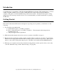
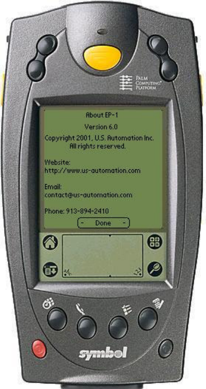
Introduction Congratulations on your purchase of the US Automation EP1 Barcode Scanner. This manual refers to your new scanner as the EP1, which is based on Symbol’s SPT 1700 Series scanner with an integrated Palm OS computer. This guide covers the installation/setup of the barcode scanner. All units are tested prior to being shipped and can be used upon arrival; however, it is recommended that you read this manual before operating the EP1 unit.
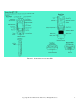
FIGURE 1. OVERVIEW OF YOUR NEW EP1 Copyright © 1999-2002 US Automation Inc., All Rights Reserved.
FIGURE 2. HOW TO CHARGE YOUR EP1. Copyright © 1999-2002 US Automation Inc., All Rights Reserved.
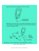
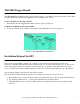
TRG3000 Trigger Handle The TRG3000 Trigger Handle adds a pistol grip with a trigger to your EP1, increasing ergonomic comfort when using the terminal in scan-intensive applications for extended periods of time. To insert the EP1 into the trigger handle: 1. Slide the EP1 into the trigger handle until it locks into place (see figure 3). To Remove the EP1 from the trigger handle: 2. To remove the EP1, press down the release spring and pull the EP1 forward (see figure 3). FIGURE 3. EP1 TRG3000 TRIGGER HANDLE.
From the main desktop, start up the EP1 application (see figure 4, item 1). Note: Your EP1 application may not be in the same location as the picture below, but the icon will look the same. FIGURE 4. EP1 APPLICATION STARTUP Copyright © 1999-2002 US Automation Inc., All Rights Reserved.
Options Button Then press the options button (Menu Icon) figure 5, item 1 shown below. FIGURE 5. OPTIONS MENU Copyright © 1999-2002 US Automation Inc., All Rights Reserved.
Mode Selection From the Options listed, select Mode (figure 6, item 1 shown below). FIGURE 6. MODE SELECTION Copyright © 1999-2002 US Automation Inc., All Rights Reserved.
Mode Menu The mode determines what kind of error proofing the EP1 will perform, and therefore what kind of barcode labels will be required. From the Options listed in figure 7, select one of the following modes: 1. Part Number – checks to make sure part numbers match, requires 2 barcode labels one pick ticket and one parts bin label. 2. Job Sequence Number – checks for a valid Job Sequence Number, requires 1 barcode label with JSN only. 3.
The following are valid barcode formats for part numbers. Parts Bin 10020099 10020099 0099 0099 10020099 10020099 Pick Ticket 10020099 0099 10020099 0099 20099 099 As long as there is some difference between the pick ticket and parts bin barcode format, the EP1 can determine if the user has made mistakes like scanning 2 pick tickets in a row, or scanning 2 parts bins in a row, and will report any such deviation as an error.
The following are valid barcode formats for JSN / Part number mode. Parts Bin 10020099 10020099 0099 0099 10020099 10020099 Pick Ticket 10003001.10020099 3001.0099 10003001.10020099 10003001.0099 10003001.20099 03001.099 NOTE: It is required that you use at least 5 digits for the JSN portion of the barcode which would be 99999 jobs before a roll over of job sequence numbers occurs.
FIGURE 7. MODE MENU Copyright © 1999-2002 US Automation Inc., All Rights Reserved.
FIGURE 8. PART # PICK TICKET BARCODE EXAMPLE FIGURE 9. PART # PARTS BIN BARCODE EXAMPLE Copyright © 1999-2002 US Automation Inc., All Rights Reserved.
Scanning 1-D Bar Codes with the EP1 The EP1 has an integrated laser bar code scanner that allows you to collect data by scanning bar codes. To scan bar codes with the EP1: 1.) Start your scanning application. 2.) Aim the scanner at the bar code. 3.) Press either the right, left, center or trigger handle (if purchased) scan trigger. Make sure the red scan beam covers the entire barcode. The green scan LED lights and a beep sounds to indicate a successful decode. FIGURE 10. HOW TO SCAN A 1-D BARCODE LABEL.
Scanning PDF417 (2-D) Bar Codes with the EP1 The EP1 is capable of scanning 2-dimensional bar codes. To scan a 2-dimensional PDF417 bar code: 1.) Aim the scanner at the PDF bar code and press the trigger. 2.) Hold the trigger down and keep the scan line parallel to the rows of the symbol 3.) Manually raster the scan line by slowly moving the scanner up and down so it scans the entire barcode at a rate of one inch per second. The PDF decode feedback should be enabled upon arrival.
Pick Ticket Setup Press the Options button (Menu Icon, see figure 5, item 1). Select the Pick Ticket Setup (figure 12, item 1 shown below). FIGURE 12. PICK TICKET SETUP Copyright © 1999-2002 US Automation Inc., All Rights Reserved.
Pick Ticket Setup Menu Press the Clr All button (see figure 13, item 1 below). Then scan a sample pick ticket barcode by pressing the barcode scan button (see figure 13, item 2 below), and press the OK button (see figure 13, item 3 below). Now the EP1 knows what kind of pick ticket barcode you are using. FIGURE 13. PICK TICKET SETUP MENU Copyright © 1999-2002 US Automation Inc., All Rights Reserved.
Parts Bin Setup Press the Options button (Menu Icon, see figure 5, item 1). From the Options listed select the Parts Bin Setup (see figure 14, item 1 below). FIGURE 14. PARTS BIN SETUP Copyright © 1999-2002 US Automation Inc., All Rights Reserved.
Parts Bin Setup Menu Press the Clr All button (see figure 15, item 1 below). Then scan a sample pick ticket barcode by pressing the barcode scan button (see figure 15, item 2 below), and press the OK button (see figure 15, item 3 below). Now the EP1 knows what kind of parts bin barcode you are using. FIGURE 15. PARTS BIN SETUP MENU Copyright © 1999-2002 US Automation Inc., All Rights Reserved.
Counters Selection Press the Options button (Menu Icon, see figure 5, item 1). From the Options listed select Counters (see figure 16, item 1 below). FIGURE 16. COUNTERS SELECTION Copyright © 1999-2002 US Automation Inc., All Rights Reserved.
Counters Menu The Counters menu (see figures 17 & 18) allows users or supervisors to track and clear all information related to bar codes. Figure 17 & 18 (left side) show the Part Number Counter Menu. The only difference between figures 17 & 18 (left side) is shown in figure 18, item 4 (JSN button). The JSN button appears because the DUAL JSN option mode is checked. Pressing the JSN button will display the menu in figure 18 (right side) and item 7 shows the Parts Button replacing the JSN button spot.
Counter Explanations Pick Ticket / Parts Bin Counter Menu Correct Matches: This counter will tell how many Pick Ticket and Parts Bin barcodes were matched. This number should match real close to your actual jobs (see figure 17 or 18, item 1). No error messages will appear. Mismatches: This counter will tell how many Pick Ticket and Parts Bin barcodes were mismatched (see figure 17 or 18, left side). An error message is generated for every count.
JSN Counter Menu Correct Sequences: This counter will tell how many barcodes were successfully scanned in the correct sequence. This number should come real close to your actual number of parts scanned (see figure 18, item 5). Sequence Errors: This counter will tell how many barcodes were scanned out of sequence. This type of error will generate an error message (see figure 18, item 6). Wrong Length: This counter will tell how many barcodes of the wrong length were scanned out of sequence.
FIGURE 18. PICK TICKET/PARTS BIN & JSN (DUAL OPTION) COUNTER MENUS Copyright © 1999-2002 US Automation Inc., All Rights Reserved.
What Happens When an Operator Encounters an Error? As everyone knows even the best operator will eventually make a mistake when picking parts. The EP1 will detect an invalid part selection and report it as an error. When an error is detected by the EP1, the EP1 will display a pop up box indicating the reason for the error while sounding an audible alarm.
History Options Menu The History menu (see figure 19) allows users or supervisors to view the history records. The EP1 can keep a history of scan results in its local database. A history of scans will be kept if the EP1 is operated in a mode that uses a JSN for error proofing. Histories are not kept for parts mode only. At this time the history database is 32000 records in size. The database will automatically wrap around and write over the oldest records when it is full.
JSN History Menu The JSN History menu (see figure 20) allows users or supervisors to view the history records. Press the Display button (see item 1, Figure 20) to see a list of all the records. If you know the JSN number you want to see, use the stylus and tap on the 0 in item 2 (figure 20), then tap item 4 (figure 20) and type the JSN number. Once you see your JSN on the line in item 2, tap the Display button (item 1, figure 20).
JSN History Display The JSN History Display (see figure 21) shows the history records. In the history window you will see the Date, Time, and the JSN. When a record is highlighted, you will see what the status of that scan was (see item 1, figure 21). For example, you might see Scan Error, JSN mismatch, No Scan, Part Number Match, or JSN Match. See Counter Error Explanations or Counter Errors for more detail on the status of the scans. FIGURE 21.
Alerts Options Menu The Alerts Options Menu (see figure 22) allows users or supervisors to setup one or more part numbers to alert them via a pop-up window containing text to warn the user that a particular part has been scanned. This feature enables users to get special notifications for part a number that requires extra attention. For example if a part number is encountered where there is an option that is rarely used, then the alert message can notify the operator to double check that part.
Alerts Menu The Alerts Menu screen(see figure 23) shows a list of alerts that have been setup. This menu also allows users to edit alerts that have already been setup, or to add or delete alerts from the list (see Item 1, Figure 23). Figure 23 shows us that No Alerts have been setup. To set up your first alert, select the Add button with your stylus (see Item 1, Figure 23). FIGURE 23. ALERTS MENU Copyright © 1999-2002 US Automation Inc., All Rights Reserved.
Edit Part Number Alert Menu The Edit Part Number Alert screen (see figure 24) allows an alert to be entered or edited. First tap the line next to the Part Number with your stylus (see item 1, figure 24). To enter the part number call up the numeric keyboard as shown on item 4, Figure 25. When entering the Parts Bin Part Number NOTE: That you must enter ALL digits of the part number. For example if it is an 8-digit part number, then enter all 8 digits.
FIGURE 25. KEYBOARD NUMBERS AND LETTERS MENUS Copyright © 1999-2002 US Automation Inc., All Rights Reserved.
Alerts Setup Completed Menu The Alerts Setup Completed Menu (see Figure 26), shows 3 parts bin part numbers as being setup to display a pop up box containing the text of your choice when these parts bin numbers are scanned (see Figure 27). The user may edit, add, or delete part numbers from this menu (see item 1, Figure 26). FIGURE 26. ALERTS SETUP COMPLETED MENU Copyright © 1999-2002 US Automation Inc., All Rights Reserved.
Part Number Alert Box The Part Number Alert Box (see item 1, Figure 27) appears when a parts bin part number has been set up as an alert. When the number is scanned, the operator will see a box like this containing the text that was entered when the alert was setup. The Operator MUST tap the OK button with their stylus to continue scanning part numbers. FIGURE 27. PART NUMBER ALERT BOX Copyright © 1999-2002 US Automation Inc., All Rights Reserved.
Is Your EP1 Scanner Ready to Use? Your EP1 scanner should be ready for use after the following checklist is complete: 1.) The unit is fully charged (see figure 2). 2.) A mode of operation has been selected and set (see page 11). 3.) The new barcode labels have been printed out and match the mode that you have selected. 4.
Troubleshooting Symptom Possible Causes and remedies EP1 terminal does not turn on: Low battery warning after Replacing the battery: No sound: EP1 terminal shuts itself off: EP1 terminal doesn’t recognize My handwriting: • • • Adjust the contrast control. Make sure the battery is fully charged & installed properly. Replace the battery.
EP1 terminal doesn’t recognize My handwriting Continued: • • Tapping the screen buttons or icons does not activate the corresponding feature: Beamed data does not transmit: When receiving beamed data an out of Memory message appears: Your EP1 unit does not read A barcode: Make sure you are writing the strokes for letters in the lefthand side, and the strokes for numbers in the right-hand side of the Graffiti writing area. Make sure that Graffiti is not shifted into extended or punctuation modes.
Your EP1 unit does not read A barcode continued: • • • • • • Check to make sure the bar code label is not defaced. If the problem is with a Pick Ticket label only, the most common problem is the printer not printing the bars correctly. Be sure you are within proper scanning range Be sure the unit is programmed to accept the type of barcode you are scanning. If you are expecting a beep on a good decode and don’ t hear one, check to see that the application is set to generate a beep on a good decode.
Index A M Alerts Menu........................................................... 32 Alerts Options Menu ............................................. 31 Alerts Setup Completed Menu .............................. 35 Mode Menu ..................................................... 11, 14 Mode Selection...................................................... 10 C Counter Errors .................................................... 27 Counter Explanations ............................................
Copyright © 1999-2002 US Automation Inc., All Rights Reserved.