T4x-Series QuickStart Guide Publication # 821002560
Datalogic Automation, Inc. 6301 West Old Shakopee Rd Suite A Bloomington MN 55438 USA T4x-Series™ Reference Manual Edited: 07/2013 © 2013 Datalogic Automation, Inc. ALL RIGHTS RESERVED. Protected to the fullest extent under U.S. and international laws. Copying or altering of this document is prohibited without express written consent from Datalogic Automation, Inc. (DLA) Datalogic and the Datalogic logo are registered trademarks of Datalogic S.p.A. in many countries, including the U.S.A. and the E.U.
REFERENCES REFERENCES CONVENTIONS This manual uses the following conventions: "User" refers to anyone using an T4x-Series camera. "Camera" refers to a T4x-Series camera (T40, T47, or T49). "You" refers to the System Administrator or Technical Support person using this manual to install, configure, operate, maintain, or troubleshoot a T4x-Series camera. REFERENCE DOCUMENTATION For further details refer to the Impact Reference Guide provided as supplementary documentation on the installation CD.
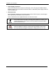
COMPLIANCE COMPLIANCE For installation, use, and maintenance, it is not necessary to open the camera. Opening the camera will void the warranty. Connect Ethernet and dataport connections to a network which has routing only within the plant or building and no routing outside the plant or building.
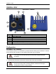
GENERAL VIEW GENERAL VIEW T4x-Series™ Camera 6 5 7 1 2 8 3 1 2 3 4 5 6 7 8 4 Power Indicator LED Power, Serial Interface, and I/O Connector MAC Address label Ethernet Connector Ethernet Network Presence LED Not Used – No Connection Indicator Lights (see page Error! Bookmark not defined.) Reset and Camera Button Event (see page 8) Configuration ASSEMBLE THE CAMERA The first step to perform is to assemble any accessories that make up the T4x-Series™ camera. A lens must be used.
T4x-SERIES QUICKSTART GUIDE 2. Remove the sensor protection label (dust cap) by pulling it off of the base. 3. Mount a lens by slowly screwing it onto the base until it arrives at the mechanical stop. Anti-vibration components (optional) Protective Film on front of cover (remove before calibration) Lens Cover Lens Camera Figure 1 – Assembling the Camera and Lens 4. To keep dust and dirt off of the lens during mounting, temporarily replace the lens cover.
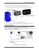
CONNECT THE SYSTEM • Power Supply Connection Use the PG-120 power Kit (3 versions for European, UK or US plug) and CAB-PG-0002 + BA400 connector to connect the PG-120 to the CBX. An alternative power supply to the PG120 is the PWR-120. • CBX Connection Use CAB-SCSxx between the T4x-Series camera and the CBX for power, external trigger device (photocell), and additional I/O connections. Use the CAB-GE0x for the Gigabit Ethernet connection to the host.
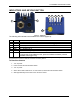
T4x-SERIES QUICKSTART GUIDE INDICATORS AND KEYPAD BUTTON 3 4 5 6 7 2 1 8 Figure 2 - Indicators The following LED indicators are located on the camera (Figure 2): 1 2 3 4 5 6 7 8 POWER NET ONLINE OUT1 OUT2 OUT3 BUSY BUTTON On – camera is connected to power On – Ethernet link is established.
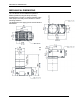
MECHANICAL DIMENSIONS MECHANICAL DIMENSIONS The T4x-Series can be installed to operate in different positions using the body mounting bracket shown in Figure 3. Use the fourteen screw holes (M4) on the body of the camera for custom mounting solutions. The diagrams on this page give the overall camera dimensions.
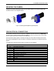
T4x-SERIES QUICKSTART GUIDE MOUNTING THE CAMERA Using the T4x-Series mounting brackets, you can obtain rotation on the various axes of the camera as shown in the diagrams below. Figure 3 –Positioning with Body Mounting Bracket (Back) CBX ELECTRICAL CONNECTIONS All T4x-Series cameras can be connected to a CBX500 connection box using a CAB-SCSxx accessory cable. These accessory cables terminate in a 19-pin connector on the camera side and in a 25-pin male D-sub connector on the CBX side.
POWER SUPPLY Outputs Power Source - Outputs Power Reference - Outputs Output 1 + Output 1 Output 2 + Output 2 Strobe + / Output 3 + (See Note) Strobe - / Output 3 RS232 Interface TX Transmit RX Receive SGND Signal Ground (See Caution) Note: The strobe signal connection is shared with Output 3. If a non-zero value is defined for the Strobe Pulse Length value (in VPM – Impact – General), the strobe is active. If the value is zero, Output 3 is active.
T4x-SERIES QUICKSTART GUIDE RS232 SERIAL INTERFACE The signals relative to the following serial interface types are available on the CBX spring clamp terminal blocks. The serial interface parameters (baud rate, data bits, etc.) are defined in Vision Program Manager (VPM) software. Refer to the Serial Port section of the Impact Reference Guide (Publication # 843-0093). The following pins are used for RS232 interface connection.
INPUTS Debounce Filter. Refer to the Camera Setup tab section in the Impact Reference Guide for further details. These inputs are optocoupled and can be driven by both NPN and PNP type commands. Polarity insensitive inputs assure full functionality even if pins A and B are exchanged.
T4x-SERIES QUICKSTART GUIDE EXTERNAL TRIGGER INPUT CONNECTIONS USING EXTERNAL POWER Vext 30 Vdc max. EXTERNAL TRIGGER Camera V VCC + ~ ~ A I1A B I1B - Signal I in Figure 8 - PNP External Trigger Using External Power Vext 30 Vdc max.
OUTPUTS INPUT 2 CONNECTIONS USING EXTERNAL POWER Vext 30 Vdc max. INPUT DEVICE Camera V VCC + ~ ~ - D I2A E I2B Signal I in Figure 12 - PNP Input 2 Using External Power Vext 30 Vdc max. INPUT DEVICE Camera VCC + ~ ~ - D I2A E I2B V Signal Figure 13 - NPN Input 2 Using External Power OUTPUTS Three optocoupled general purpose outputs are available. The meaning of the outputs can be defined by the user.
T4x-SERIES QUICKSTART GUIDE Note: The strobe signal connection is shared with Output 3. If a non-zero value is defined for the Strobe Pulse Length value (in VPM – Impact – General), the strobe is active. If the value is zero, Output 3 is active. CAUTION Power is available directly to the Output Device, independently from the Power Supply Switch inside the CBX.
SOFTWARE CONFIGURATION CAUTION Power is available directly to the strobe, independently from the Power Supply Switch inside the CBX. Configure the Strobe Signal in the VPM software. Refer to the Camera Setup tab section of the Impact Reference Guide. Figure 18 – External Illuminator Connections This table summarizes the External Illuminator wiring and power requirements.
T4x-SERIES QUICKSTART GUIDE 4. To be able to communicate, the client and device’s IP addresses for the local area connection must be configured. The vision device is shipped with a factory default IP address of 192.168.0.128 and a default mask of 255.255.255.0. If you need to change the device’s IP address or mask, do so before installation. 5. Insert the Impact Installation CD in the drive. 6. The installation program should start. Select the language you want the install to use, then click OK. 7.
SOFTWARE CONFIGURATION Changing the Client’s IP Address (Windows 7) IMPORTANT NOTE: Change only the Local Area Connection named LAN1 or LAN2. These correspond to Ethernet Ports 1 and 2 on the front of the processor. DO NOT change any of the other Local Area Connections. Changing any other connection can cause the M-Series cameras to stop functioning. 1. In the Start menu, click on Control Panel. 2. Under Network and Internet, click on View Network Status and Tasks. 3.
T4x-SERIES QUICKSTART GUIDE 5. In the list of items, select Internet Protocol Version 4 (TCP/IPv4), then click Properties. 6. Select Use the following IP address. 7. Enter the desired IP address. 8. Click OK to close all the open dialog windows.
TECHNICAL FEATURES TECHNICAL FEATURES ELECTRICAL FEATURES Power Supply Voltage Consumption (max) Communication Interfaces RS232 Ethernet Inputs Input 1(External Trigger) and Input 2 Max. Voltage Max. Input Current Outputs Output 1, Output 2 and Strobe/Output 3 VOut (ILoad = 0 mA) Max. VOut (ILoad = 10 mA) Max. PD = VOut x ILoad Max. 10-30 Vdc ± 20% T40 – 1 A ( Max); T47 – 1.05 A ( Max); T49 – 1.
www.datalogic.