
Manual


DC Power
AC Power
2
2
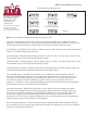
Figure # 2
Output Selection Switches (SW3)
4-20mA Out
4-20mA Out
3
4
4
3
AC/DC Power
AC/DC Power
0-10 VDC
0-5 VDC Out
ON
1
ON
1
4
4
3
3
ON
2
2
1
1
ON
J2
Cable to remove from J2 Connector
Red
Black
Green
1
2 3
4
ON
4 5 6
3
ON
1
SW2
SW3
J2
4-20
VAC
GND
0-5V
mA
or or
VDC 0-10V
Red
Wire
BLK
Wire
Green
Wire
Switch Settings (SW2)
Figure # 2
Normal Operating Condition
4
5 6
32
1
ON
4 to 20mA Output
0 to 5 VDC or 0 to 10 VDC Output
Supply Ground / Common
+15 to 36 VDC Supply Voltage
1
2 3
4
ON
4 5 6
3
ON
1
SW2
SW3 (see Figure #2
to the Left)
J2
4-20
GND
VDC
Vout
Red Wire
BLK Wire
Green Wire
J3
4 to 20mA Output
0 to 5 VDC or
0 to 10 VDC Output
Supply Ground / Common
+15 to 36 VDC Supply Voltage
2
2