
Installation manual
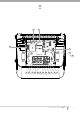


Owner Installation Instructions GDO-9 15
WARNING: The opener must be securely
fastened to structural supports, otherwise opener
failure may ensue causing serious personal injury
and/or property damage.
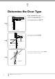
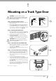
Step 3 - Determine Bracket Position
Open the door and fi nd the highest point of travel of
the top door panel.
Using a level, transfer this height to the wall above
the door (Fig. 10) and mark a line 60mm above it.
Determine the centre point on the wall above and on
top of the door. Draw two lines extending 21.5mm
from each side of the centre point. (Fig. 11)
Step 4 - Mounting the Wall Bracket
Centre the bracket over the intersection of these two
lines. Mark centres for at least two holes (Fig. 11)
and ensure it is into a solid mounting point.
Drill holes into the wall with an appropriate bit.
Secure to the wall using:
IF CONCRETE OR BRICK - 8mm (5/6”) loxins/dynabolts.
IF TIMBER - wood screw #20 or similar (min. 50mm).
WARNING: Make sure concrete, brick wall or
timber lintels are solid and sound so as to form a
secure mounting platform.
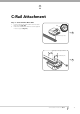
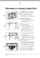
Step 5 - Attach the Rail to the Wall Bracket
Attach the C-Rail assembly to the wall bracket
with the 90mm long clevis pin and secure with the
supplied snap pin (Fig. 12)
Leave the drive unit in its packing box for protection
during installation.
Step 6 - Secure the Drive unit to the Ceiling
Raise the drive unit from the packing box and support
it in the horizontal position with a step ladder.
Open the garage door. Rest the opener on the open
door and use a scrap piece of wood to bring it to
horizontal level.
Line up the track perpendicular to the wall.
Secure the perforated angle (not supplied) to the
ceiling above where drive unit’s mounting holes will
be once fully installed. A representative mounting is
shown (Fig. 13)
Connect the drive unit to the ceiling mounted
perforated angle with M8x20mm screws and nuts.
Strips should not extend more than 18mm below
centre of drive unit mounting holes.
Go to Step 11 on page 17.
a.
b.
c.
a.
b.
c.
a.
b.
a.
b.
c.
d.
e.
10
fi g
11
fi g
Track
Door
Track
Level
Level
Door
Drilled holes
Mounting on a Track Type Door
12
fi g
13
fi g
Structural member
43
21.5
21.5