
Instruction manual

B&D Doors is a division of B&D Australia Pty Ltd
P: 13 62 63
W: www.bnd.com.au
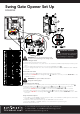
Sliding Gate Opener Set Up
NeoSlider
TM
V2
IMPORTANT WARNING!
Do not connect battery or solar panel
polarity incorrectly - this will result in
serious damage to components.
6
7
2
9
8
11
3
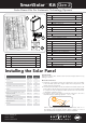
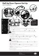
Mount the Charger Board
a. Unplug the drive unit from mains power.
b. Remove the main cover, then remove the transformer, EMC board (if fitted) and mains power cable.
c. Mount the Charger Board inside the cover using four (4) M4x8 screws
11
.
d. Plug the Charger Board’s three wire harness (red/yellow/black) into the control board’s “SBC-02” connector.
Connect the Solar Panel
a. Feed the Solar Panel’s
1
cable through black grommet on the chassis.
b. Connect the red wire to the Charger Board’s
3
“SOLAR+” connector, and the black wire to the “-SOLAR”
connector.
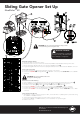
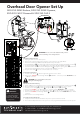
WARNING! The opener will become active
during the following steps.
Mount & Connect the Battery
a. Drill a 16.0mm hole in the Battery Pack enclosure (recommend at the bottom) and fit nylon gland
9
.
b. Mount the Battery Pack
2
using the mounting lugs
6
and screws
7
close to the opener.
c. Feed the 2-core 18awg gauge cable
8
through the Battery Box’s nylon gland
9
.
d. Connect the red wire to the Battery Box’s “+” terminal, and the black wire to the “–” terminal
e. Feed the other end of the 2-core 18awg gauge cable
8
through the drive unit’s black grommet.
f. Connect the red wire to the Charger Board’s
3
“BAT+” connector, and the black wire to the “–BAT”
connector.
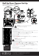
Setup and Test the Opener
a. Select Menu 7 on the control board, press “SET”, select Sub Menu 7 (“Battery/Solar”) and enable using
the “OPEN” and CLOSE” buttons.
b. Setup travel limits and transmitters as per the slider instruction manual.
c. Press either “OPEN” or “CLOSE” buttons, or use a transmitter to operate the gate.
d. Refit the main cover.
WARNING! Do not connect the batteries until you have
connected wiring on the charger board.
1