
Installation manual


8
GDO-9v2 Enduro™ Owner Installation Instructions
Gen 2
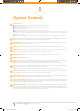
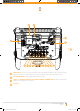
Opener Controls
01
02
03
04
05
06
07
08
09
10
Terminal Block.
V+ is used to power devices such as Wireless PE Beam, external receiver etc.
EB1 first Safety Beam input.
0V (Input) is a 0 volt connection for PE Beam, external receiver, osc, aux etc.
EB2 second Safety Beam input.
0V (Input) is a 0 volt connection for PE Beam, external receiver, osc, aux etc.
O/S/C INPUT is used for the connection of a wired switch (momentary contact). This switch can then be used to
open, stop or close the door. Install the wall switch in a location where the switch is out of reach of children and
the garage door is visible.
AUX output can be used to control another device (such as alarm system etc) via the opener’s remote control.
SET button (orange) is used during the installation phase together with the OPEN and MINUS (-) buttons to set
the door limit positions. The SET button is also used to re-initialize the opener.
LIGHT CODE button (white) is used for storing or erasing the transmitter button (code) you wish to use to switch
the courtesy light on the opener on or off.
CODING LED (red) light flashes when a code is being stored or when a transmitter button is pressed.
OPERATE button (yellow) is used during installation to test the open, stop and close cycles for the opener. The
opener has to be initialised by the SET button to make the O/S/C button operable.
DOOR CODE button (blue) is used for storing or erasing transmitter buttons for door operation
DOOR STATUS LED (yellow)
MINUS (-) button (red) is used during installation to help set the close limit position. Pressing and holding this
button will move the door in the close direction. Movement stops when the button is released.
NOTE: The safety obstruction detection is inoperable when the MINUS (-) button is used to move door.
PLUS (+) button (green) is used during installation to help set the open limit position. Pressing and holding this
button will move the door in the open direction, releasing stops the door.
NOTE: The safety obstruction detection is inoperable when the PLUS (+) button is used to move door.
CLOSE LIMIT LED (red) the LED is very helpful during installation. It illuminates and flashes when the door is
closing and remains steady on when the close limit position has been reached.
OPEN LIMIT LED (green) the LED is very helpful during installation. It illuminates and flashes when the door is
opening and remains steady on when the open limit position has been reached.
AUTO CLOSE TIME button (white) is used to adjust the auto close time. While holding the AUTO CLOSE
TIME button and then pressing the PLUS (+) button the time is increased. Each press will increase the time by 1
second. Pressing the MINUS (-) button will decrease the time.
FORCE MARGIN SET button: the obstruction force margin is set automatically during installation. The margin
can be adjusted manually using the Force MARGIN SET BUTTON (white). Holding the MARGIN SET BUTTON and
pressing PLUS (+) or MINUS (-) buttons will increase or decrease the amount of force. The Force Margin Set should
only be used if environmental factors (wind, etc.) affect the door’s operation.
11
12
13
GDO-9v2GEN2 User Manual v101.indd 8 15/11/2012 10:07:36 AM