GDO-9v2 Enduro™ Gen 2 Overhead Garage Door Opener Featuring TrioCode™ Technology Technical Document Installation Manual 1.01 v 26 JULY 2012 English Part # 13289 (Manual) INSTALLATION INSTRUCTIONS | OWNERS COPY GDO-9v2GEN2 User Manual v101.
WARNING: It is vital for the safety of persons to follow all instructions. Failure to comply with the installation instructions and the safety warnings may result in serious personal injury and/or property damage. Please save these instructions for future reference.
GDO-9v2 Enduro™ Gen 2 Overhead Garage Door Opener Important Safety Instructions 4 Features 6 Opener Controls 8 Kit Contents 10 Installation 11 C-Rail Attachment 11 Determine Door Type 12 Mounting - Track Type Door 13 Mounting - Spring Loaded Door 14 Mounting Door Bracket & Arms 15 Wired Safety Beam Installation 23 16 Auto-Close Setup 24 Setting Speed Mode 16 Battery Backup Installation 25 Setting Travel Limits - Control Panel 17 SmartSolar™ Installation 26 Setting Travel Li
Important Safety Instructions WARNING: It is vital for the safety of persons to follow all instructions. Failure to comply with the following safety instructions may result in serious personal injury and/or property damage. CAUTION: If your garage has no pedestrian entrance door, an emergency access device should be installed. This accessory allows manual operation of the garage door from outside in case of power failure.
Important Safety Instructions The unit should be installed so that it is protected from the elements. It should not be exposed to water or rain. It is not to be immersed in water or sprayed directly by a hose or other device. The garage door must be well balanced. Sticking or binding doors must be repaired by a qualified garage door installer prior to installation of the opener. Frequently examine the installation, in particular cables, springs and mountings for signs of wear, damage or imbalance.
Features Thank you for purchasing the Automatic Technology GDO-9v2 Enduro™ Gen 2 Overhead Garage Door Opener. Designed to suit sectional overhead and one piece tilt up doors, the components and materials used ensure this opener will provide years of smart, simple and secure operation. Listed below are some of the many features: Operation To open or close the door simply press a button on a TrioCode™ handheld transmitter, a wall mounted transmitter, or optional wall switch for two seconds.
SmartSolar™ and Battery Backup Compatibility (optional) The opener can be fitted with a SmartSolar™ or Battery Backup kit for operation in the event of a power outage, or where mains power access is not available. NOTE: If the door is the only entrance to the garage, and a battery backup kit is not fitted, a keyed cable release should be fitted externally to the garage.
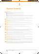
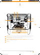
Opener Controls 8 01 Terminal Block. 02 SET button (orange) is used during the installation phase together with the OPEN and MINUS (-) buttons to set 03 LIGHT CODE button (white) is used for storing or erasing the transmitter button (code) you wish to use to switch 04 CODING LED (red) light flashes when a code is being stored or when a transmitter button is pressed. 05 OPERATE button (yellow) is used during installation to test the open, stop and close cycles for the opener.
17 16 15 01 14 fig 01 02 03 04 05 06 07 08 09 10 11 12 13 14 PROG INPUT is used to connect the Automatic Technology Handheld Programmer ‘PG-3’ for editing control 15 JP1 CONNECTOR the shunt must be fitted for solar operation. 16 17 and receiver functions, accessing diagnostic tools, and activating special features and operating modes. SBCO2 J4 STANDBY BATTERY OR SOLAR CHARGER CONNECTOR the shunt must be plugged if battery or solar charger is not connected.
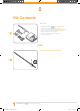
Kit Contents Drive Unit 1 x GDO-9v2 Enduro™ Gen 2 drive unit (Fig. 02) 1 x TrioCode™ Transmitter pack (Fig. 02) (Pack includes two keyring transmitters and batteries) 1 x Wall mount transmitter with battery (Fig. 02) 2 x Door attachment arms (Fig. 02) 1 x Accessory and hardware pack (Fig. 02) 1 x Installation Manual fig 02 PLUS Pre-Assembled Single Piece C-Rail fig 03 10 GDO-9v2 Enduro™ Gen 2 Owner Installation Instructions GDO-9v2GEN2 User Manual v101.
C-Rail Attachment Single piece C-Rails are pre-tensioned during manufacturing for transport. Some extra tension may be required after installation. Shaft If the C-Rail needs to be shortened or lenghtened (using the extension kit) ensure these modifications are made to the drive unit end. fig 04 Locate shaft into sprocket Step 1 - Secure C-Rail to Drive Unit a. b. Locate and insert the shaft of drive unit into the CRail’s sprocket (Fig. 04).
Determine the Door Type Step 2 - Determine Door Type Determine which type of garage door you have as illustrated below. (Fig. 06 to Fig. 08) . For a sectional (panel) door on tracks (Fig. 06) proceed with the installation from Step 3. Track fig 06 Door Sectional door with track Header wall Track For a one-piece door on tracks (Fig. 07) proceed with the installation from Step 3. Door fig 07 Highest point of travel One piece door with track For a one-piece door without tracks (on springs) (Fig.
Mounting on a Track Type Door WARNING: The opener must be securely fastened to structural supports, otherwise opener failure may ensue causing serious personal injury and/or property damage. 60mm b. c. 60mm Level fig Step 3 - Determine Bracket Position a. Level Open the door and find the highest point of travel of the top door panel. Using a level, transfer this height to the wall above the door (Fig. 9) and mark a line 60mm above it.
Mounting on a Spring Loaded Door WARNING: The opener must be securely fastened to structural supports, otherwise opener failure may ensue causing serious personal injury and/or property damage. Centre of Door Step 7 - Determine the Door’s Centre a. fig 13 b. Find the centre of the door and mark this location both above the door and on top of the door. Draw two lines 21.5mm either side of this (Fig. 13). Step 8 - Prepositioning the Opener a. b. c. Raise the door to open position.
Mounting Door Bracket & Arms Step 11 - Mounting Door Bracket The door bracket comes in two parts. The bottom plate with two mounting holes is used on its own for one piece doors. For sectional doors, the top plate is placed over the bottom plate and is fixed with four (4) screws (Fig. 17). a. b. fig 17 Mount the door bracket, or bracket assembly, on the door’s centre line one-third down the top panel (Fig.
Setting Speed and Limits Step 13 - Setting Speed Mode The default speed of the opener has been set to suit the majority of applications. However, there are three speed modes available if required:1. 2. 3. fig 21 Slow - to suit one piece door without tracks Medium ( default ) - suits majority of applications Fast - to suit some sectional applications The speed settings can only be changed before setting the travel limits. If the opener speed needs to be changed please complete the steps below.
Setting Speed and Limits Setting Travel Limits : Via Control Panel Step 13.1 - Setting Travel Limits NOTE: If Safety Beams are to be used they must be installed before setting the travel limits. WARNING! Use caution when operating the manual release with the door open since it may fall rapidly due to weak or broken springs, or an improperly balanced door. fig 22 CAUTION! Do not disengage the opener to manual operation with children, persons or any objects including motor vehicles within the doorway. a. b.
Setting Speed and Limits Setting Travel Limits : Via Transmitter The GDO-9v2 Enduro™ Gen 2 has the alternate ability to set travel limits using the transmitter, allowing free movement around the garage to better assess the desired limit positions. Step 14.1 - Code a Transmitter for Limit Setting a. fig 25 b. c. d. Ensure the opener is powered up and button cover is removed. Press and hold the DOOR CODE button (Fig. 25). Press Button 1 on the transmitter for two seconds (Fig. 26).
Safety Obstruction Forces Safety Obstruction Force Test WARNING! Take care when testing or adjusting the Safety Obstruction Force. Excessive force may cause SERIOUS PERSONAL INJURY and/or PROPERTY DAMAGE. WARNING! Photo electric beams must be installed if the closing force at the bottom edge of the door exceeds 400N (40kg) force. fig 27 Step 15.1 - Testing Close Cycle a. b. c. Press the OPERATE button to open the door (Fig. 27).
Safety Obstruction Forces Adjusting Safety Obstruction Force The Safety Obstruction Force is calculated automatically during setup. Adjusting this is normally only necessitated by environmental conditions such as windy or dusty areas, and areas with extreme temperature changes. WARNING! Photo electric beams must be installed if the closing force at the bottom edge of the door exceeds 400N (40kg) force. fig 29 Step 16.1 - To Increase Force Pressure a. b. c. d. e. Hold down FORCE MARGIN SET button (Fig.
Coding Transmitters Step 17.1 - Code a Transmitter Button for Door Operation a. b. c. d. e. Ensure the button cover is removed Press and hold the DOOR CODE button (Fig. 32). Press one of the four buttons on the transmitter for two (2) seconds, pause for two (2) seconds, then press the same button again for two (2) seconds. Release the DOOR CODE BUTTON. Press the transmitter button to test. fig 32 Step 17.
Coding Transmitters Step 18 - Remotely Coding Transmitters Using this method transmitters can be coded without access to the opener’s control panel as long as a precoded transmitter is available. IMPORTANT NOTE: The door or courtesy light must activate when the steps below are performed. This indicates that the pre-coded transmitter is in range of the opener, and the correct button has been pressed. fig 36 a. b. c. d. fig 37 e. Take any pre-coded transmitter.
Wired Safety Beams Installation Step 19 - Safety Beams (optional) Safety Beams extend across the garage door opening. The Safety Beam is designed to detect an obstruction while the door is closing and to send a signal to the garage door opener to reverse or stop the door movement. One or two sets of Safety Beams can be connected to GDO-9v2 Enduro™ Gen 2 opener. 6 4 3 fig 39 Step 19.1 - Fitting the Safety Beam a. b. c. d.
Wired Safety Beams Installation Step 19.2 - Safety Beam Failure Emergency Close When the user finds that they are unable to move the door and suspect that it is due to a faulty SAFETY BEAM they can attempt to enter Safety Beam Failure Emergency Close mode by press and holding a pre-coded button on the remote control or OSC button on the console for five seconds. Auto-close Setup WARNING: It is compulsory to have Safety Beams installed when using Auto-Close mode.
Battery Backup Installation fig 44 Battery Backup Installation Step 21.1 - Connect the Battery Back Up Kit a. b. c. d. e. f. g. h. Step 21.2 - Testing Battery Back Up Disconnect power to the opener. Remove screws and swing open the cover (Fig 44). Mount the PCB support with two screws item # 13. Secure the SBC0-2 Charger Board onto the PCB support with three (3) screws item #14. Feed the 2-wire battery harness item # 10 through the grommet on the base plate and connect to SBCO-2 battery charger board.
SmartSolar™ Installation WARNING: Do not connect batteries until Step 22.3 Step 22.1 - Mount the Charger Board a. b. Fig 45 c. d. e. Unplug the drive unit from mains power. Remove the screws, swing open the main cover and remove the light diffuser. Then remove the transformer, EMC board (if fitted) and mains power cable. Mount the PCB support with two screws .Secure the SOL charger board on to PCB support with 3 screws. (Fig. 45).
Final Setup Step 23 - Setting of Courtesy Light Time The preset courtesy light time is three minutes. This time can only be changed by “PG3” programmer. Step 24 - Setting the Pet Mode position The default Pet Mode height can be changed as follows: a. Drive and stop the door at the desired Pet Mode open position by pressing OPERATE button on the console or the transmitter button coded for O/S/C operation. b.
Default Settings & Specifications Factory default settings Default Step Maximum Courtesy light time 3 Mins. 4 Mins. Obstruction force margin 0.7 Amps 0.1 Amps 2.0 Amps Auto close time 0 Secs 1 Sec. 255 Secs. Speed Mode Medium 1 Fast Maintenance counter 3000 Cycles - - Technical specifications 28 Power supply 230V - 240V AC 50Hz 220V AC 60Hz Export Model Transformer rating 24V DC Standby power 2.
Door Status Indicators Door Opener State OPEN LED (Green) Open On CLOSE LED (Red) Close Opening STATUS LED (Yellow) Beeper On Flashing Closing Flashing Door travel stopped Flashing Door obstructed when opening Flashing Flashing Door obstructed when closing Flashing Opener overloaded Alternating flashes Door in open position with AutoClose mode selected One second flashes Pet Mode Engaged On Mains power interrupted Rapid flashes Beeps as door moves Alternating flashes On Service
Troubleshooting Guide Symptom Possible cause Remedy Door will not operate Mains power not switched on Switch on mains power Door is obstructed Remove obstruction Door is locked or motor jammed Unlock door or remove jam Door tracks/hardware damaged Door requires service/repair by qualified technician Adverse weather conditions (wind or cold) causing door to stiffen and become tight in the tracks Increase force margin setting.
Maintenance Maintenance Maintenance counter To ensure a long and trouble free life for your opener, the following is recommended: At this time Automatic Technology recommends you contact your door professional to perform an annual door service. Whilst your opener does not require any periodic maintenance, the door that it is fitted to, does. Your garage door is a large, heavy, moving object and should be tested regularly to ensure it is in good condition.
Parts List GDO-9v2 Enduro™ Gen 2 Owner Installation Instructions GDO-9v2GEN2 User Manual v101.
GDO-9v2GEN2 User Manual v101.
Important Safety Checks Please refer to the risk assessment table below and ensure all the necessary controls are in place.
Warranty and Exclusion of Liability 1. This Warranty is given by Automatic Technology (Australia) Pty Ltd (ABN 11 007 125 368) (ATA), 6-8 Fiveways Boulevard, Keysborough 3173, 1300 133 944, sales@ata-aust.com.au 2. The Competition and Consumer Act 2010 (including the Australian Consumer Law) and other relevant statutes provide a set of statutory consumer guarantees and other legal rights that cannot be excluded, restricted or modified by contract.
© July 2012 Automatic Technology (Australia) Pty Ltd. All rights reserved. TrioCode™ is a trademarks of Automatic Technology (Australia) Pty Ltd. No part of this document may be reproduced without prior permission. In an ongoing commitment to product quality we reserve the right to change specification without notice. E&OE.