
Troubleshooting guide


Owner Installation Instructions GDO-9v2 SecuraLift
®
25
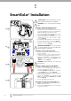
Battery Back Up Installation
Step 25.1 - Connect the Battery Back Up Kit
Disconnect power to the opener.
Remove screws and swing open the cover (Fig. 44).
Mount battery pack and secure with item 4 and 10.
Mount the SBY-3 Charger Board on three hex
spacers pre mounted on base and secure with
three (3) M4 x 8 screws.
Feed the 2-wire battery harness through the
grommet on the base plate and connect to SBY-3.
Feed charger harness from SBY-3 to the control
board and plug into the 4 pin connector marked
SBY-3 onto the control board.
WARNING: After Step 25.1(g) the opener may
become active (even when power is off). This is a
result of a residual charge in the batteries.
Connect battery harnesses item 3 and 7 together
(Fig. 44).
Reconnect power.
a.
b.
c.
d.
e.
f.
g.
h.
44
Fig
Step 25.2 - Testing Battery Back Up
Press either the OPERATE button or transmitter
to test the opener.
Whilst door is in motion disconnect mains
power the door should continue to operate as
normal.
NOTE: Wait for the door to complete its travel.
Press the OPERATE button or transmitter to
activate the door.
Whilst door is in motion re-connect power. The
door should complete the cycle as normal.
Step 25.3 - Troubleshooting
If door stops or moves very slowly under battery
power, the batteries may be weak or have no
charge. Connect mains power and allow the
batteries to charge. This may take 24 - 48 hours to
reach maximum charge capacity.
a.
b.
c.
d.
Item Description Qty Order Code
1. SBY-3 Version 1.00 1 00852
2. SBY-3 charger harness 1 14115
3. SBY-3 battery harness 1 15660
4. Pan head screw w/washer M4 x 8 7 10320
5. Batteries cover 1 16460
6. Batteries 12V sec 12-2.2 AGM type 2 15470
7. Battery harness 1 15670
8. Battery coupling wire 1 12005
9. Batteries support 1 16480
10. Hexagon standoff M4 2 11190
Battery assembly (#01660)
4. Connect
1. Remove screws &
swing cover to open
5. Close cover and
re-secure with screw
3. Mount battery and
secure with item 4 & 10
2. Connect wires as shown.
Refer to wiring diagram.
2 3
4 1
10
4
1
2
3
7
8
10
10
11
5
6
9
Wiring diagram