
Installation manual

TUBE/PIPE ASSEMBLY
- 8 -
©Copyright 2006 Automatic Technology
IMPORTANT SAFETY INSTRUCTIONS FOR INSTAL-
LATION
Warning: Incorrect installation can lead to severe injury.
Follow ALL installation instructions.
CHECK OPERATION OF DOOR BEFORE BEGINNING
THE INSTALLATION OF THE SECURALIFT® AUTO-
MATIC OPENER CHECK THE OPERATION OF THE
DOOR.
The door must be well balanced and be in a reasonable
operating condition. You should be able to lift the door
smoothly and with little resistance. It should stay open
around 900mm to 1200mm above the floor. The door
should not stick or bind in the guide tracks. The ideal
operational effort in raising or lowering the door should
not exceed a force of 15kg Make sure that all door
locks are either released, or disabled and remove
unnecessary accessories.
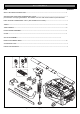
STEP 1
Slide shuttle assembly onto tube (one piece only) and
locate it in approximately half way position.
Please note: Arrow on shuttle must point towards
garage door.
To assemble the rest of the tubes, always slide short
insert tube half way into the long tube, then slide other
tube onto remaining portion of insert tubes. Continue
this process with remaining tube until desired length is
achieved.
STEP 2
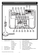
The opener is supplied with an 8 teeth drive sprocket on
the drive unit. If the opener is to be fitted to a one piece
door without track, exchange the 8 teeth sprocket on
drive unit, with a 7 teeth drive sprocket available as an
option from Automatic Technology.
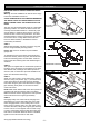
STEP 3
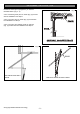
Attach one end of chain to chain index screw, nearer to
drive unit, using one joint link. (Fig. 1). Proceed to wrap
chain around drive unit sprocket and chain spreader,
then follow along the pipe to the idler wheel on support
pipe assembly, finally attach to the other end of the
chain index screw.
NOTE: Make certain that the teeth of the drive sprocket are
engaged in the chain and that the chain is not twisted.
Make sure that the chain is engaged in the chain spreader
and the idle wheel on the support pipe assembly.
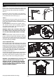
STEP 4
Disengage trolley from chain index by swinging lever
downward (Fig. 2), then slide trolley away from chain
index along pipe track. Loosen locking nuts on chain
index screws. To tighten chain, turn chain index in anti-
clockwise direction, looking from support pipe assembly
to drive unit. Do not over-tighten chain as it has to sag
6-12mm. Check before locking screw with locking nuts
that chain is not twisted. When the tension is finalized,
tighten lock nuts at both ends of chain index.
Fig. 2
Fig. 1
Fig. 2a
SECOND CHAIN
JOINT LINK
FIRST CHAIN
JOINT LINK
LOCKING NUTS
SHUTTLE ASSY
DISENGAGED POSITION
ENGAGED POSITION