
Installation manual

OPERATING CONTROLS
- 5 -
©Copyright 2006 Automatic Technology
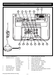
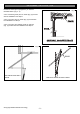
1. P. E. SHUNT. The shunt has to
be removed when connecting a
Photo Electric Beam.
NOTE: P.E. SHUNT must not be
removed otherwise the opener will
not function correctly. Remove only
when a P.E beam is to be
connected.
PROG INPUT is used for the
connection of the ATA Handheld
Programmer for the purpose of
editing control and receiver
functions.
2. Terminal Block. 24V PWR is used
to power devices such as photo
electric beams.
PE (Input) for photo electric beam
for safety and auto-close function.
LGT (Input) allow hard wired
external trigger for the opener’s
courtesy light.
O/S/C INPUT is used for the
connection of a wired switch
(momentary contact). This switch
can then be used to open, stop or
close the door. Install the wall switch
in a location where the switch is out
of reach of children and the garage
door is visible.
3. SET button (yellow) is used dur-
ing the installation phase together
with the Open and Close buttons to
set the door limit positions. The Set
button is also used to re-initialize the
Opener.
4. OPERATE button (Yellow) is
used during installation to test the
open, stop and close cycles for the
opener. The opener has to be
initialized by the Reset button
before the O/S/C button becomes
operable.
5. PLUS (+) button (green) is used
during installation to help set the
open limit position. Pressing and
holding this button will move the
door in the open direction.
Movement stops when the button is
released.
NOTE: The open safety obstruction
detection is inoperable whenever
the Open or Close Drive button is
used to move door.
6. OPEN LIMIT LED (green) the
led is very helpful during installation.
It illuminates and flashes when the
door is opening and remains steady
on when the open limit position has
been reached.
7. FORCE MARGIN SET Button
The obstruction force pressure is
set automatically by the opener
during installation. The pressure can
be adjusted manually using the
Force Margin Set button (White).
Holding the Force Margin Set button
and pressing the Plus (+) or Minus
(-) button will increase or decrease
the amount of force. The Force
Margin Set is only ever used if other
environmental factors (wind, etc.)
effect the operations of the
door/opener.
8. LIGHT CODE button (white) is
used for storing or erasing the
transmitter button (code) you wish
to use to switch the courtesy light on
the opener on or off.
9. CODING LED (red) light flashes
when a code is being stored or
when a transmitter button is
pressed.
10. DOOR CODE button (blue) is
used for storing or erasing the
transmitter button you wish to use to
command the door to open, stop or
close.
11. DOOR STATUS LED (Yellow)
12. MINUS (-) button (red) is used
during installation to help set the
close limit position. Pressing and
holding this button will move the
door in the close direction.
Movement stops when the button is
released.
NOTE: The close safety obstruction
detection is inoperable whenever
the Open or Close Drive button is
used to move door.
13. CLOSE LIMIT LED (red) the led
is very helpful during installation. It
illuminates and flashes when the
door is closing and remains steady
on when the close limit position has
been reached.
14. DATUM ADJUST SCREW is
used during limits set up to indicate
the mid point of the door’s travel.
15. AUTO CLOSE TIME button
(White) is used to adjust the auto
close time. While holding in the auto
close button and then pressing the
open button the time is increased.
Each press will increase the time by
5 seconds. Pressing the close
button will decrease the time.
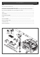
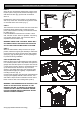
16. ENGAGE/DISENGAGEMENT
CORD when pulled down and
released this will select manual
mode on the opener, particularly
when there is a power failure.
Pulling down and again releasing
will select automatic mode on the
opener. The length of the string is
adjustable.
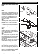
17. EASY ACCESS TRANSMIT-
TER The “manual release”
engage/disengagement handle has
within its housing a wireless
transmitter. If the button is pressed it
will open, stop or close the garage
door.