
Installation manual


STEP 15
SETTING TRAVEL LIMITS POSITIONS
METHOD ONE: VIA THE CONTROL PANEL
IMPORTANT NOTE: The OPERATE button will not
function until the open and close limits positions are set.
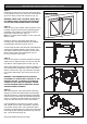
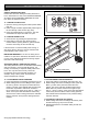
15.1 SETTING DATUM POSITION
1. Move the door manually to engage the shuttle
assembly onto the chain index.
2. Turn power on - the Close Limit LED should be
flashing.
3. Press and hold Minus (-) or Plus (+) button to move
the door to half way open position.
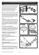
3. Using a small blade screw driver turn the datum
adjust screw slowly until the yellow status LED just
illuminates.
Note: If the status LED is already illuminated when the
door is half way up then turn the datum adjust screw
until the LED goes off then turn back one notch to illumi-
nate again.
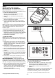
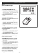
15.2 SETTING LIMITS POSITIONS
NOTE: The door and shuttle must be engaged into the
chain index and should be open approximately half way.
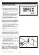
1. Press red Minus (-) button and hold it, the door will
start closing. Release the button once you have
reached your desired closed limit position. (Fig. 21)
2. Press the set button. This action will store into
memory the closed limit position.
3. Press the green Plus (+) button, the door will start
opening. Release the button once you have reached
your desired open limit position.
IMPORTANT WARNING: Please be aware that the
garage door will start closing automatically once step 4
is performed. The door will also automatically re-open
after fully closing with a small pause between the
cycles.
4. Press the Set button. This action will store into
memory the door limit position. The door will now
automatically close to its limit position then fully open
to calculate the safety obstruction forces (ISS).
Please be aware of the above warning.
The opener can now be operated via the OPERATE
Button.
WARNING: DO NOT TURN DATUM ADJUST SCREW
AFTER LIMIT SETTING, OTHERWISE OPENER WILL
NOT FUNCTION CORRECTLY.
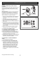
15.2 RESETTING DOOR LIMIT POSITIONS
The door travel limit positions can be deleted for new
positions by the following steps below:
1. Press and hold the Close button (Fig. 21) for six (6)
seconds until you hear three beeps and the red
Close Limit LED starts to flash. Release the button.
2. Follow STEPS 15.1 and 15.2 to set new travel limit
positions.
Go to STEP 17 and test the Safety Obstruction
Force.
Fig. 20
Fig. 19
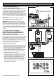
Fig. 21
SETTING LIMITS
- 14 -
©Copyright 2006 Automatic Technology