
Installation manual

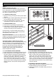

STEP 9
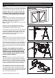
Determine the centre of the door and mark this location
on the wall above and on top of the door. Then draw two
(2) lines 21.5mm on each side of the door. (Fig. 10).
WARNING; MAKE SURE CONCRETE, BRICK WALL
OR TIMBER LINTELS ARE SOLID AND SOUND SO
AS TO FORM A SECURE MOUNTING PLATFORM.
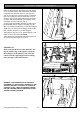
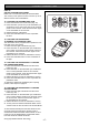
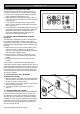
STEP 10
Raise the door to open position. Rest the opener on the
top edge of the door with end of the pipe/tube against
the header wall and drive unit support level with the
lowest point of the open door. (Fig. 11).
Note: Do not slide opener tube/pipe on face of the door
when it is open.
Secure the opener to the ceiling above drive unit
mounting holes, with perforated angle (not supplied).
A representative mounting is shown. (Fig. 9)
Connect angle and drive unit with 2 flat perforated strips
of angle (not supplied) with M8 x 20mm screws, nuts
and washer. Strips should not extend more than 18mm
below centre of drive unit mounting holes. (Fig. 9).
Do not lock screws at this stage.
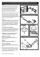
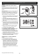
STEP 11
Close the door slowly. The opener pipe/tube will be ele-
vated by the top edge of the door as it moves. Stop the
door when it is at its highest point of travel. (Fig. 12)
Allow 25mm additional height for clearance between the
door and the track. Support pipe / tube in this position
and the close the door. (Fig. 12) This will be the height
to mount the wall bracket. Top of door must not touch
tube.
WARNING: THE OPENER MUST BE SECURELY
FASTENED TO A STRUCTURAL SUPPORT OF THE
GARAGE. FAILURE TO FASTEN THE OPERATOR
CORRECTLY WILL LEAD TO POSSIBLE OPENER
FAILURE CAUSING SERIOUS PERSONAL INJURY
AND/OR PROPERTY DAMAGE.
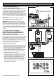
STEP 12
With the centre point of the door located, mark a line
through the centre of the wall bracket onto the header
wall (above the door). Using the bracket as a template
mark a minimum of two holes and drill with appropriate
size bit. If necessary the wall bracket can be anchored
using more than two holes for a more secure fitting.
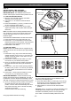
If the wall bracket is mounted onto concrete or brick
wall, use M8 or 5/16” loxins or dynabolts. If mounted
onto wooden lintel or beam, use wood screws #20 or
equivalent, minimum 50mm long. Attach the wall bracket
to the support pipe assembly with 90mm long clevis pin
(Fig. 13) and securely spring clip.
Fig. 10
Fig. 11
Fig. 12
MOUNTING ON A SPRING LOADED DOOR
- 12 -
©Copyright 2006 Automatic Technology
Fig. 13