
Installation manual

STEP 5
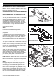
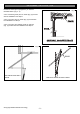
Open the door and find the highest point of travel of the
top door panel. Using a level, transfer this height to the
wall above the floor (Fig. 6) and mark a line 60mm
above it.
Determine the centre of the location on the wall above
and on top of the door. Then draw two (2) lines 21.5mm
on each side of the door centre. (Fig. 7).
STEP 6
The intersection of line at 21.5mm from door centre and
line 60mm above highest point of travel are centre
points, where holes for mounting of wall bracket should
be drilled. (Fig. 7)
If the wall bracket is mounted onto concrete or brick
wall, use 8mm or 5/16” loxins or dynabolts. If mounting
onto wooden lintel or beam, use wood screw #20 or
equivalent minimum 50mm long.
WARNING: MAKE SURE CONCRETE, BRICK WALL
OR TIMBER LINTELS ARE SOLID AND SOUND SO
AS TO FORM A SECURE MOUNTING PLATFORM.
STEP 7
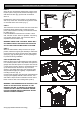
When the wall bracket is firmly secured in its proper
position, attach the support pipe assembly to wall brack-
et with 90 mm long clevis pin and secure with supplied
spring clip, (Fig. 8) leaving drive unit in its packing box
for protection during installation.
STEP 8A (METHOD ONE)
Raise the drive unit from the packing box and support it
in a horizontal position with a step ladder, then open the
garage door. Rest the opener on the open door and use
a scrap piece of wood to bring it to horizontal level. Line
up the track with the centre line on top of the door.
Secure to the ceiling above drive unit mounting holes,
with perforated angle (not supplied). A representative
mounting is shown. (Fig. 9)
Connect angle and drive unit with 2 flat perforated strips
of angle (not supplied) with M8 x 20mm screws, nuts
and washer. Strips should not extend more than 18mm
below centre of drive unit mounting holes. (FIG. 9).
WARNING: THE OPENER MUST BE SECURELY FAS-
TENED TO A STRUCTURAL SUPPORT OF THE
GARAGE. FAILURE TO FASTEN THE OPERATOR
CORRECTLY WILL LEAD TO POSSIBLE OPENER
FAILURE CAUSING SERIOUS PERSONAL INJURY
AND/OR PROPERTY DAMAGE.
Fig. 6
Fig. 7
Fig. 9
MOUNTING ON A TRACK TYPE DOOR
- 10 -
©Copyright 2006 Automatic Technology
Fig. 8