® GDO-7V1 SecuraLift Overhead Garage Door Opener Installation Instructions OWNERS COPY P/N 13228 Warning: It is vital for the safety of persons to follow all instructions. Failure to comply with the installation instructions and the safety warnings may result in serious personal injury and/or property and remote control opener damage. Please save these instructions for future reference.
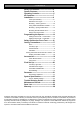
CONTENTS Safety Precautions---------------------------3 Opener Features------------------------------4 Operating Controls---------------------------5 Kit Contents------------------------------------7 Installation--------------------------------------8 Tube Pipe Assembly---------------------------8 Determine Door Type-------------------------- 9 Mounting - Track Type Door-----------------10 Using inbuilt antivibration brackets---------11 Mounting - Spring Loaded Door------------12 Mounting Door Bracket & Arm
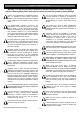
SAFETY PRECAUTIONS Warning - It is vital for the safety of persons to follow all instructions. Failure to comply with the following Safety Rules may result in serious personal injury and/or property damage. Caution: If your garage has no pedestrian entrance door, an emergency access device should be installed. This accessory allows manual operation of the garage door from outside in case of power failure. The unit should be installed so that it is protected from the elements.
FEATURES Thank you for purchasing the ATA SecuraLift® Automatic Garage Door Opener. This opener is designed to suit sectional overhead and one piece tilt up doors. The components and materials used in this opener are of the latest technology and highest quality. Listed below are some of the many features. OPERATION To open or close the door simply press the hand held transmitter, the wall mounted transmitter, or optional wall switch for two seconds.
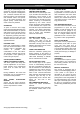
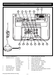
OPERATING CONTROLS 1. P. E. SHUNT. The shunt has to be removed when connecting a Photo Electric Beam. NOTE: P.E. SHUNT must not be removed otherwise the opener will not function correctly. Remove only when a P.E beam is to be connected. PROG INPUT is used for the connection of the ATA Handheld Programmer for the purpose of editing control and receiver functions. 2. Terminal Block. 24V PWR is used to power devices such as photo electric beams.
OPERATING CONTROLS 1 4 3 8 9 7 6 5 10 2 11 12 13 14 15 16 1. 2. 3. 4. 5. 6. PE SHUNT, PROG INPUT TERMINAL BLOCK - 24V (Pwr) 0V (Gnd) PE (Trigger) LGT (Light Trigger) OSC (Operate) Com (Common) SET BUTTON (ORANGE) OPERATE BUTTON (YELLOW) PLUS (+) BUTTON (GREEN) OPEN LIMIT LED (GREEN) ©Copyright 2006 Automatic Technology 7. 8. 9. 10. 11. 12. 13. 14. 15. 16.
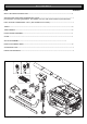
KIT CONTENTS ITEM QUANTITY GDO-7 SECURALIFT® DRIVE UNIT-------------------------------------------------------------------------------------------1 SECURACODE ® KEY RING TRANSMITTER PACK---------------------------------------------------------------------1 pack includes two keyring transmitters two batteries and one wall mount bracket for ptx4 transmitter EASY ACCESS TRANSMITTER - EAT-1 (Not available some models)-----------------------------------------------1 TUBES---------------------------------------
TUBE/PIPE ASSEMBLY IMPORTANT SAFETY INSTRUCTIONS FOR INSTALLATION Warning: Incorrect installation can lead to severe injury. Follow ALL installation instructions. CHECK OPERATION OF DOOR BEFORE BEGINNING THE INSTALLATION OF THE SECURALIFT® AUTOMATIC OPENER CHECK THE OPERATION OF THE DOOR. The door must be well balanced and be in a reasonable operating condition. You should be able to lift the door smoothly and with little resistance. It should stay open around 900mm to 1200mm above the floor.
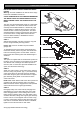
DETERMINE THE DOOR TYPE Determine which type of garage door you have as illustrated below. (Fig. 3 -5). Fig. 3 z For a sectional (panel) door on tracks (Fig. 3) proceed with the installation from Step 5. z For a one piece door on tracks (Fig. 4) proceed with the installation from Step 5. z For a one piece door without tracks (on springs) (Fig. 5) proceed with the installation from Step 9. Fig. 5 Fig.
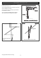
MOUNTING ON A TRACK TYPE DOOR STEP 5 Open the door and find the highest point of travel of the top door panel. Using a level, transfer this height to the wall above the floor (Fig. 6) and mark a line 60mm above it. Fig. 6 Determine the centre of the location on the wall above and on top of the door. Then draw two (2) lines 21.5mm on each side of the door centre. (Fig. 7). STEP 6 The intersection of line at 21.
USING ANTI VIBRATION BRACKETS STEP 8B (METHOD TWO) Raise the drive unit from the packing box and support it in a horizontal position with a step ladder, then open the garage door. Rest the opener on the open door and use a scrap piece of wood to bring it to horizontal level. Line up the track with the centre line on top of the door. Secure to the ceiling above drive unit mounting holes, with perforated angle (not supplied). A representative mounting is shown. (Fig.
MOUNTING ON A SPRING LOADED DOOR STEP 9 Determine the centre of the door and mark this location on the wall above and on top of the door. Then draw two (2) lines 21.5mm on each side of the door. (Fig. 10). Fig. 10 WARNING; MAKE SURE CONCRETE, BRICK WALL OR TIMBER LINTELS ARE SOLID AND SOUND SO AS TO FORM A SECURE MOUNTING PLATFORM. STEP 10 Raise the door to open position.
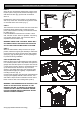
MOUNTING DOOR BRACKET AND ARMS STEP 13 The door bracket comes in two parts. The bottom plate with two mounting holes is used on its own for any one piece doors. The top plate is placed over the bottom plate and uses 4 mounting holes for extra strength. This is used on sectional doors. (See Fig. 14). Mount the door bracket to the centre line of the door using M6 or equivalent screws (not supplied) Alternatively it can be welded on steel doors. Fig.
SETTING LIMITS STEP 15 SETTING TRAVEL LIMITS POSITIONS METHOD ONE: VIA THE CONTROL PANEL IMPORTANT NOTE: The OPERATE button will not function until the open and close limits positions are set. Fig. 19 15.1 SETTING DATUM POSITION 1. Move the door manually to engage the shuttle assembly onto the chain index. 2. Turn power on - the Close Limit LED should be flashing. 3. Press and hold Minus (-) or Plus (+) button to move the door to half way open position. 3.
SETTING LIMITS STEP 16 SETTING TRAVEL LIMIT POSITIONS METHOD TWO: VIA THE TRANSMITTER IMPORTANT NOTE: The OPERATE button will not function until the open and close limits positions are set. INCH OPEN BUTTON 1 Fig. 22 INCH CLOSE BUTTON 4 16.1 SETTING DATUM POSITION 1. Move the door manually to engage the shuttle assembly onto the chain index. 2. Turn power on - the Close Limit LED should be flashing. 3. Press and hold Minus (-) or Plus (+) button to move the door to half way open position. 4.
SETTING SAFETY OBSTRUCTION FORCE STEP 17 SAFETY OBSTRUCTION TEST Please take care when testing the Safety Obstruction Force. Excessive force may cause SERIOUS PERSONAL INJURY and/or PROPERTY DAMAGE can result from failure to follow this warning. Fig. 25 17.1 TESTING CLOSE CYCLE 1. Open the door by pressing the Yellow Operate button (Fig. 25). 2. Place a length of timber approximately 50mm high on the floor directly under the door (Fig. 25a). 3. Press the Operate button to close door.
CODING TRANSMITTERS STEP 18 SETTING TRANSMITTERS CODES Make sure to connect the battery to the transmitters. The memory in the openers receiver can store up to 24 different remote control transmitters. Fig. 26 18.1 STORING THE TRANSMITTERS CODE 1. Press and hold the Door Code button (Fig. 26). 2. Press the button (one of four) on the transmitter you would like to use to control the door for two seconds, pause for two seconds. Press the same button again on the transmitter for two seconds. 3.
CODING TRANSMITTERS STEP 19 STORING TRANSMITTER(S) FROM A REMOTE LOCATION Using this method you don’t need to have access to the control panel on the Door Opener. However, you do need a transmitter that is pre coded to the controller’s receiver. Fig. 27 IMPORTANT NOTE: The Door or Courtesy Light must be activated when the step below is performed. The moving Door or Light switching on is to confirm from a remote location that, the correct button was pressed, and the transmitter is in range of the Opener.
P.E. BEAM AND AUTO CLOSE 21. FITTING THE SAFETY PHOTO ELECTRIC BEAM SENSOR (OPTIONAL) Locate the Photo Electric Beam (P.E.) normally closed contact type in a strategic location within doorway. We recommend 150mm above the floor level and as close as possible to the door opening, inside the garage. Remove shunt from P.E connector (Fig. 29) and connect the wires from the P.E. wiring harness to terminal block (Fig. 30). The wiring diagram is for Model PHBE (Order Code 90214).
FINAL SET UP 23. SETTING OF COURTESY LIGHT TIME The preset courtesy light time on the door opener is 3 minutes. This time can be changed by the following: 1. Press in and hold both the Auto Close Time button and Force Margin Set button (Fig. 32). 2. While holding in the two buttons, press the Plus (+) button. Each press of the button will add 10 seconds to the light time. 3. To decrease the time follow Step 1 and press the Minus (-) button. Each press will deduct 10 seconds from the light time. 4.
PARAMETERS DOOR STATUS INDICATORS OPEN LED GREEN DOOR OPENER STATE OPEN CLOSE LED RED DOOR STATUS LED YELLOW BEEPER ON ON CLOSE FLASHING OPENING FLASHING CLOSING DOOR TRAVEL STOPPED FLASHING DOOR OBSTRUCTED WHEN OPENING FLASHING FLASHING DOOR OBSTRUCTED WHEN CLOSING FLASHING OPENER OVERLOADED ALTERNATING FLASHES DOOR IN OPEN POSITION WITH AUTO CLOSE MODE SELECTED ONE SECOND FLASHES BEEPS WHILE DOOR IS MOVING ALTERNATING FLASHES RAPID FLASHES MAINS POWER INTERRUPTED DOOR STATUS INDICA
DEFAULT SETTINGS AND SPECIFICATIONS FACTORY DEFAULT SETTINGS MAXIMUM MOTOR RUN TIME COURTESY LIGHT TIME DEFAULT STEP MAXIMUM 30 Secs. — — 4 Mins 10 Secs. 10 Mins. 3 1 27 0 Secs. 5 Secs. 4 Mins.
SYSTEM SPECIFICATIONS Maximum residential overhead garage door area 16.5m2 Door Load Rated Load: Push pull force Short term peak load Supply Voltage 230 - 240 V AC 50Hz Motor Type 1/3 H.P. (AC) Alternating Current Current Max. 5A Globe Edison (screw mount) 240V 60W Rough Service (or construction type) Limit Adjustment Electronic - semi-automatic Force Control Electronic - fully automatic. Can be adjusted for environmental reasons Transmitter Frequency 433.92MHz Powerhead Weight 7.
TROUBLE SHOOTING SYMPTOM POSSIBLE CAUSE REMEDY Door will not operate. Mains power not switched on. Door is obstructed. Door is locked or motor jammed. Door tracks/hardware damaged. Switch on mains power. Remove obstruction. Unlock door or remove jam. Door requires service/repair by qualified technician. Turn off “Vacation Mode” The opener is in “Vacation Mode” Door starts to close but automatically reverses to open position. Door operates from drive unit (OPERATE) button but not from transmitter.
MAINTENANCE RECORD MAINTENANCE RECORD Record any maintenance in the following table to assist in any warranty service. DATE MAINTENANCE PERFORMED BY ©Copyright 2006 Automatic Technology - 25 - SIGNATURE AMOUNT INV. No.
PARTS LIST WHEN ORDERING SPARE PARTS PLEASE QUOTE THE ORDER CODE NUMBER TO YOUR INSTALLER/DEALER Item No. Description Order Code Item No. Description Order Code 1 BASE PLATE SUB ASSEMBLY-------------------02152 38 PAN SERRATION HEAD SCREW M4x12-------------10380 2 BUSH 127ID 18---------------------------------------04261 39 PAN HEAD SCREW W/WASHER M4x10-------------10340 3 AC MOTOR IT 0.
PARTS LIST ©Copyright 2006 Automatic Technology - 27 -
WARRANTY AND EXCLUSION OF LIABILITY 1. This warranty is an addition to any non-excludable conditions or warranties that are implied into this contract by relevant statute, including the Trade Practices Act 1974 (Cth). 2.