PN13240 GDO-8V2 EasyRoller®II Weather Resistant Roll Up Door Opener INSTALLATION INSTRUCTIONS | OWNERS COPY
WARNING: It is vital for the safety of persons to follow all instructions. Failure to comply with the installation instructions and the safety warnings may result in serious personal injury and/or property and remote control opener damage. Please save these instructions for future reference.
GDO-8v2 EasyRoller® II Roll Up Garage Door Opener Safety Warnings 4 Product Features 6 Operating Controls 8 Package Contents 10 Side Room Requirements 11 Fixing Weight Bar 11 Fitting Locking Bar Covers 11 Mounting The Opener 12 Fixing Curtain To Drum 13 Setting Limits Via Control Panel 13 Setting Limits Via Transmitter 14 Setting Obstruction Force Margin (ISS) 15 Re-Calculating Force Margin Sensitivity 15 Coding Transmitters 16 Deleting Transmitters 16 Locking the Control Pane
Important safety instructions WARNING: It is vital for the safety of persons to follow all instructions. Failure to comply with the following Safety Rules may result in serious personal injury and/or property damage. FOR ADDITIONAL SAFETY protection we strongly recommend the fitting of a Photo Electric (P.E.) Beam. In most countries P.E. Beams are mandatory on all garage doors fitted with automatic openers. For a small additional outlay Automatic Technology recommends that P.E.
Important safety instructions The EasyRoller® II is not intended for use by young children or infirm persons without adequate supervision. Children should be supervised to ensure they do not play with the remote transmitters or the EasyRoller® II. Keep hands and loose clothing clear of the door and EasyRoller® II at all times. The unit is rated to IP24, however, it should be installed so that it is protected from the elements. Where possible it should not be exposed to water or rain.
Features Thank you for purchasing the Automatic Technology EasyRoller® II Automatic Garage Door Opener. Designed by our renowned engineers to suit vertical operating continuous curtain roll up doors, the EasyRoller® will provide years of smart, simple & secure convenience to your home. Operation To open or close the door simply press a button on a SecuraCode® handheld transmitter, a wall mounted transmitter, or optional wall switch for two seconds.
Lockable control panel The control panel can be locked and disabled to prevent tampering. This is useful if the opener is to be mounted on an exposed carport or a perimeter door. Locking the control panel will prevent operating the door via the Operate button, reprofiling the door, clearing limits, clearing transmitters, changing force margins, and coding transmitters.
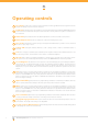
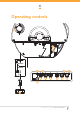
Operating controls 01 Prog input is used for the connection of the Automatic Technology PG-3 Universal Programmer for the purpose of editing control and receiver functions. 02 P.E. Shunt The shunt has to be removed when connecting a Photo Electric (P.E.) Beam. NOTE: THE P.E. Shunt must not be removed otherwise the opener will not function correctly. Remove only when a P.E. beam is to be connected. 03 Status LED (yellow) indicates when the datum adjustment screw has reached correct position.
Operating controls 15 01 02 03 06 05 11 07 08 09 10 13 12 04 14 Owner Installation Instructions GDO-8V2 EasyRoller® II 9
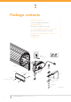
Package contents GDO-8 Easyroller® drive unit 1 PTX-4 SecuraCode® keyring transmitter 1 Alkaline battery A23 12V 1 Weight bar (not included in some models) 1 Pan head screw M4x50mm (not included in some models) 2 Nilock hex nut M4 (not included in some models) 2 Flat washer I.D.
Before installation IMPORTANT SAFETY INSTRUCTIONS FOR INSTALLATION Warning: Incorrect installation can lead to severe injury. Follow ALL instructions. Side Room Requirements Fig. 01 shows the minimum and recommended side room that is required to mount the opener. The distance between the edge of the door curtain and the inside of the bracket must be at least 40mm. However, for easier access it is recommended that at least 95mm is allowed. 85 135 40 95 fig 01 1.
Mounting the opener 4. Fixing drive unit to the door Remove U bolt Remove bracket The EasyRoller® can be fixed to the roll up garage door in a variety of ways. Described below is one method of fixing. Make sure there is enough side room to slide the drive assembly onto shaft. PLEASE NOTE: The instructions for fixing the drive assembly to the door is for right hand installation. fig 04 Fitting drive unit to door (Fig. 04, Fig. 05 and Fig. 06). 1.
Setting limits 5. Fixing of door curtain to drumwheel ° 90 The door curtain has to be secured to the drum wheel with suitable fasteners. This prevents unauthorised access through the door by pushing the curtain up and off the drum. Drum wheel 1. With the door in the fully closed position, mark the curtain (Fig. 07) on both ends of the door. 2. Open door slightly to have access to the marked positions. Secure the curtain to drum wheel using self drilling screws (two on each end).
Setting limits 6.3 Setting limits via remote control PLEASE NOTE: The opener is factory preset for installation on the RIGHT HAND SIDE. When the opener is mounted on the left side of the door the opener will travel in reverse. fig 10 Inch open button 1 Set button 2 Inch close button 4 fig 11 Switch between fast and slow inching button 3 1. Press button 4, the door will start closing. If the door starts to open - press the Operate button (Fig. 10) within two (2) seconds.
Setting safety obstruction force 8. Safety obstruction test Please take care when testing the Safety Obstruction Force. Due to Excessive forces failure to follow this warning may cause SERIOUS PERSONAL INJURY and/or property damage. The test below should be repeated at regular intervals (approximately every two months). fig 12 8.1 Testing close cycle 1. Open the door by pressing the OPERATE button (Fig. 12). 2. Place a length of timber approximately 50mm high on the floor directly under the door (Fig. 13).
Coding transmitters IMPORTANT NOTE: The door must be activated when the step below is performed. The moving door confirms that the correct button was pressed and the transmitter was in range of the opener. fig 14 Press and hold Door Code button Select one of the four buttons you wish to use to control the door Coding hole 1. Take any pre-coded transmitter. Press the button for the function you require until the door is activated and release. 2.
PE beam and final set up 13. Fitting the Photo Electric (P.E.) beam sensor (optional) Locate the P.E. Beam in a strategic location within doorway. Automatic Technology recommends 150mm above the floor level and as close as possible to the door opening, inside the garage. Remove shunt from P.E. connector (Fig. 16) and connect the wires from the P.E. wiring harness as per Fig. 17. NOTE: The wiring diagram is for an Automatic Technology Transmitter/Receiver type P.E.
Parameters Door Status Indicators Door Opener State Open LED Green Open On Close Opening Door Status LED yellow Beeper On Flashing Closing Flashing Door travel stopped Flashing Door obstructed when opening Flashing Door obstructed when closed Flashing Opener overloaded Alternating flashes Mains power interupted Rapid flashes Beeps while door is moving Alternating flashes Buttons Function Operate Opens/Stops/Closes the door Door code Codes a transmitter button for OPERATE function Fo
Default settings & specifications Factory Default Settings Default Step Maximum Maximum motor run time 30 seconds - - Obstruction force margin 8 1 - Technical Specifications Input: 230v. - 240v AC 50Hz 230V OR 115V 50 - 60 Hz ( Only In DSV Model ) Controller voltage: 24v. DC Standby power: 2.
Trouble shooting Door Status Indicators Symptom Possible cause Remedy Door will not operate Mains power not switched on. Switch on mains power. Door is obstructed. Remove obstruction. Door is locked or motor jammed. Unlock door or remove jam. Door tracks/hardware damaged. Door requires service/repair by qualified technician. Adverse weather conditions (wind or cold) causing door to stiffen and become tight in the tracks. Increase force margin setting See Step 8.3 on page 13.
Maintenance Date Maintenance performed by Signature Amount Invoive No. PLEASE NOTE: Some areas may be prone to excessive radio interference brought on by devices such as cordless telephones, wireless stereo headphones and baby monitors. It is possible that these devices could cause a degree of interference such as to greatly reduce the range of the transmitter. In such an instance please contact your Automatic Technology dealer for an alternative frequency replacement kit.
When ordering spare parts please quote the order code number to your installer/distributor Item No 1 2 3 4 5 6 7 8 9 10 11 12 13 14 15 16 17 18 19 20 21 22 23A 23B 24 25 26 27 28 29 30 31 32 33 34 35 36 37 38 Description Drive chassis sub-assy Internal gear axle Hex serration head screw M6x20 Internal gear Clamp washer Retaining ring STW 45 Mounting bracket VR1 Clutch geared motor assy 12-01 WS Transformer TDB-72-01 Kit (72VA) Ratchet timing assy Power Cord A.S. 1.
Warranty and exclusion of liability 1. This warranty is an addition to any non-excludable conditions or warranties that are implied into this contract by relevant statute, including the Trade Practices Act 1974 (Cth). 2.
Automatic Technology Pty Ltd 6-8 Fiveways Boulevard Keysborough, Victoria 3173 P 1300 133 944 E sales@ata-aust.com.au www.ata-aust.com.