
Installation manual


14
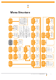
GDO-10V1 Toro
®
Owner Installation Instructions
RED
BLACK
RED
BLACK
RED
BLACK
YELLOW
R1=5.6K OHM
GREEN,BLUE,RED,GOLD
.25WATT 5% TOLERENCE
RESISTANCE
R1
YELLOW
BLACK
V+
IN
V−
P.E BEAM
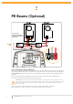
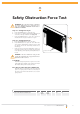
Step 5 - Fitting Photo Electric (PE) Beams
Locate the Photo Electric (PE) Beams in a strategic location in the doorway. Automatic Technology recommend that the
sensor is placed 150 mm above the fl oor level and as close as possible to the door opening. Connect as per the wiring
diagram (Fig. 09). Make sure that the sensors are correctly aligned as per the instruction manual supplied with the PE
Beams kit.
NOTE: The height of the beam installation must be chosen in such a manner that it suits the application and
environmental conditions and provide maximum safety protection.
WARNING: When using auto-close mode and PE Beams the doorway must be clear of all obstructions and
persons at all times. The location of the PE Beams and the manner in which it is installed might not give safety
protection at all times. Check to make sure that the height of the sensor and type used offers maximum
protection possible.
The wiring diagram is for Model PHBE (Order Code 90214 ) and harness kit.( Order code 01901 )
Make sure the beam is aligned correctly. Follow the manual supplied with the PE Beams.
V+
IN
V−
PE Beams (Optional)
09
fi g